| Page: |
| Home > A-Series EFI / Injection > Wet manifold injection V2.0 | |||||||
|
971 Posts Member #: 3228 Post Whore North of the Netherlands |
22nd Aug, 2011 at 09:53:18pm
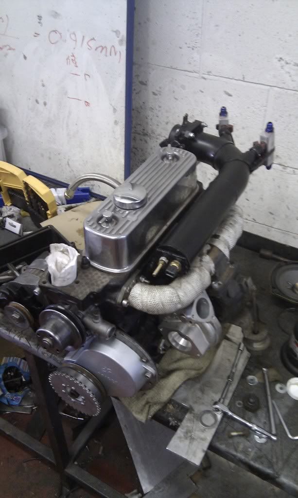
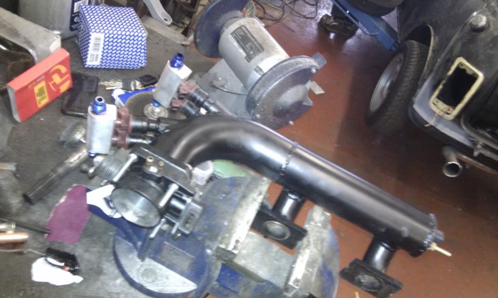
It is embarrassing, such slow progress…
Dazed and Confused.... |
||||||
|
1267 Posts Member #: 831 Post Whore Montreal, Canada |
22nd Aug, 2011 at 11:01:34pm
The injector size is more than enough but remember that you'll want to run the injectors in a 4 squirts/alternating mode with your wet manifold. That means each injector will pulse once per rev so you can't use as big a duty cycle as you would if it were once per cycle due to the additional dead time period.
|
||||||
|
971 Posts Member #: 3228 Post Whore North of the Netherlands |
24th Aug, 2011 at 10:00:03pm
Thanks for your reaction Jean.
Dazed and Confused.... |
||||||
 665 Posts Member #: 9345 Post Whore Sheffield |
25th Aug, 2011 at 10:17:50am
With a wet manifold of sufficient volume, with enough squirts per cycle, and the injectors more than 6 inches from the ports it doesn't make a significant difference where you stick the injectors in relation to the ports. Mine has 4 smaller injectors in two banks at one end of a wet manifold and I see no AFR difference between inner and outer cylinders or either port.
|
||||||
 (2)[/url] by [url=https://www.flickr.com/photos/150672766@N03/]Rod Sugden[/url], on Fli) 5988 Posts Member #: 2024 Formally Retired Rural Suffolk |
25th Aug, 2011 at 10:53:12am
Jamie, I agree your design will mostly eliminate any inner/outer differences under a wet manifold situation but I would really like to see your inner/outer AFR plots.
Edited by Rod S on 25th Aug, 2011. Schrödinger's cat - so which one am I ??? |
||||||
 665 Posts Member #: 9345 Post Whore Sheffield |
25th Aug, 2011 at 12:00:35pm
It's 1x EGO in the downpipe on this car at the moment. We are building another car which has 3x bungs in the exhaust manifold. I tested this inlet manifold on the other car to see how it was before running it on mine (and we tried another design more similar to the one Yo-Han has which it will run). I'm not running three sensors all the time as it's not something I need to know day to day. I'll swap exhaust manifolds back around at some point and get some plots once I've fixed the other problems I'm having with intermittently losing the tach signal whenever tuner studio is open, which is rather holding up the job at the moment. Just got a V3 Microsquirt to try out.. the saga continues... |
||||||
 (2)[/url] by [url=https://www.flickr.com/photos/150672766@N03/]Rod Sugden[/url], on Fli) 5988 Posts Member #: 2024 Formally Retired Rural Suffolk |
25th Aug, 2011 at 12:29:24pm
Not quite sure you can see no difference between inner/outer AFRs with only a single LSU (although Innovate do claim you can scope the single LSU and see individual pulses....) but it would be interesting to see how you are intending to do it on a turbo setup (the LSUs will surely die if you put them before the turbo straight into the manifold). Paul, myself and Graham have a sample tube arrangement to keep the LSUs at the correct temperature so I would like to see what you are intending.
Schrödinger's cat - so which one am I ??? |
||||||
 665 Posts Member #: 9345 Post Whore Sheffield |
25th Aug, 2011 at 01:09:03pm
The tach signal is brilliant as long as tuner studio isn't running. That's the bit we are working with the MS guys to figure out. F few people are having the problem and they can't replicate it..
|
||||||
 (2)[/url] by [url=https://www.flickr.com/photos/150672766@N03/]Rod Sugden[/url], on Fli) 5988 Posts Member #: 2024 Formally Retired Rural Suffolk |
25th Aug, 2011 at 01:49:16pm
Interesting.
Schrödinger's cat - so which one am I ??? |
||||||
|
857 Posts Member #: 1778 Post Whore Northants |
25th Aug, 2011 at 02:03:25pm
On the subject of widebands pre turbo, AEM have a new offering which looks interesting
|
||||||
|
1267 Posts Member #: 831 Post Whore Montreal, Canada |
25th Aug, 2011 at 02:26:58pm
That's interesting but with the number of people having trouble with calibration with AEM units, I'm not sure I would trust the output if you add the non-standard pressure compensation.
|
||||||
 665 Posts Member #: 9345 Post Whore Sheffield |
25th Aug, 2011 at 03:46:47pm
Cos I'm trying it as a crank sensor at the moment. Plus It could end up doing both jobs, but not really thought about that much yet... can't get my head round that.
On 25th Aug, 2011 Rod S said:
Interesting. Why a 36-1 wheel for the cam signal if you are considering sequential ??? A plain one gap wheel on an optoswitch works fine |
||||||
|
1267 Posts Member #: 831 Post Whore Montreal, Canada |
25th Aug, 2011 at 03:54:51pm
A 36-1 cam wheel will work for sequential but you'll lose precision compared to a crank wheel due to the slack and play in the cam drive.
|
||||||
 (2)[/url] by [url=https://www.flickr.com/photos/150672766@N03/]Rod Sugden[/url], on Fli) 5988 Posts Member #: 2024 Formally Retired Rural Suffolk |
25th Aug, 2011 at 05:47:53pm
On 25th Aug, 2011 jamie@thefatgarage said:
Cos I'm trying it as a crank sensor at the moment. Plus It could end up doing both jobs, but not really thought about that much yet... can't get my head round that. Understood.. Personally I'd keep 36:1 on the actuall crank and just a single trigger on the cam for the reasons Jean says. It's even a slight compromise on the crank if the 36:1 is on the outside of the damper pully (mine is) but a single trigger on the cam is easy, Opto or Hall. On 25th Aug, 2011 jamie@thefatgarage said:
Yes, thread hijacked! We can continue on my build thread when I update it. Sorry! Yes, sorry, Han, but I think we all agree the injectors are best not pointed towards a particular port/inlet runner for a "wet manifold" setup. Schrödinger's cat - so which one am I ??? |
||||||
|
971 Posts Member #: 3228 Post Whore North of the Netherlands |
25th Aug, 2011 at 10:21:35pm
Haha, don't worry about it.. Edited by Yo-Han on 25th Aug, 2011. Dazed and Confused.... |
||||||
|
971 Posts Member #: 3228 Post Whore North of the Netherlands |
5th Sep, 2011 at 08:07:45pm
Was looking around on the web for suitable injectors.
Dazed and Confused.... |
||||||
|
8604 Posts Member #: 573 Formerly Axel Podland |
5th Sep, 2011 at 08:37:25pm
I'm using the 60lb and 80lb Siemens injectors in the Miglia, but long style. Working OK although it's early days. Saul Bellow - "A great deal of intelligence can be invested in ignorance when the need for illusion is deep."
|
||||||
|
971 Posts Member #: 3228 Post Whore North of the Netherlands |
5th Sep, 2011 at 08:49:04pm
Thanks for that Paul.
Dazed and Confused.... |
||||||
| Home > A-Series EFI / Injection > Wet manifold injection V2.0 | |||||||
|
|||||||
| Page: |


 )
)