| Page: |
| Home > A-Series EFI / Injection > Canems ECU 1380 N/A | |||||||
|
96 Posts Member #: 7325 Advanced Member |
29th Jun, 2011 at 03:54:07pm
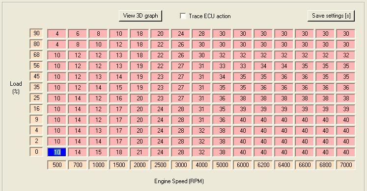
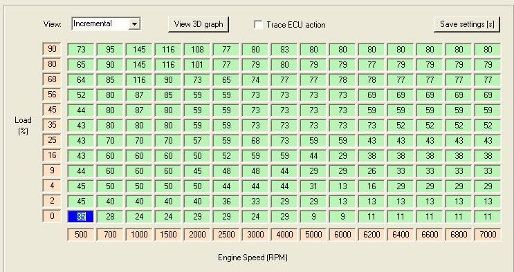
For anybody who is searching for info on the Canems ECU , I know there isnt much as I have been searching for ages! but I have one now so I suppose it would be a good Idea to share what I have.
|
||||||
|
96 Posts Member #: 7325 Advanced Member |
29th Jun, 2011 at 04:00:55pm
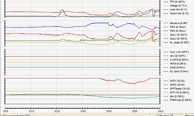
Heres a AFR from a 15min run today, as the map above was indicating a very lean mixture on the inner cylinders:
|
||||||
|
857 Posts Member #: 1778 Post Whore Northants |
29th Jun, 2011 at 05:08:27pm
Is the scale 10-20 for the afrs? Still look quite far apart.
Edited by sturgeo on 29th Jun, 2011. |
||||||
 1346 Posts Member #: 2340 Post Whore Dublin Ireland |
29th Jun, 2011 at 05:20:23pm
Looks like you getting to grips with it anyway ciaran Well done great to se somone trying somthing different :) On 17th Feb, 2009 Rob H said:
I find the easiest way is to super glue the bolt to the end of one of my fingers. ______________________________________________________ |
||||||
|
1267 Posts Member #: 831 Post Whore Montreal, Canada |
29th Jun, 2011 at 05:37:04pm
What can you adjust on the Canems ECU to equalize the AFRs? Is it still a semi-sequential injection scheme (Marcel's original method)? Does it use the MPi cam sensor signal?
|
||||||
 12307 Posts Member #: 565 Carlos Fandango Burnham-on-Crouch, Essex |
29th Jun, 2011 at 05:40:45pm
that is very lean, looks too much for just port robbing to me,
On 28th Aug, 2011 Kean said:
At the risk of being sigged... Joe, do you have a photo of your tool? http://www.turbominis.co.uk/forums/index.p...9064&lastpost=1 https://joe1977.imgbb.com/ |
||||||
|
857 Posts Member #: 1778 Post Whore Northants |
29th Jun, 2011 at 05:44:35pm
As far as I'm aware it doesn't use a cam signal but it does have a injection timing table.
|
||||||
|
857 Posts Member #: 1778 Post Whore Northants |
29th Jun, 2011 at 05:54:59pm
Does the canems include 2 wideband controllers or are they external units? Might also be worth checking the calibration on them. |
||||||
|
1267 Posts Member #: 831 Post Whore Montreal, Canada |
29th Jun, 2011 at 07:08:28pm
On 29th Jun, 2011 sturgeo said:
As far as I'm aware it doesn't use a cam signal but it does have a injection timing table. Yeah but with a semi-sequential, you can only lean out the outer cylinders by injecting outside the window. And the outer cylinders are the ones that have a tendency to be leaner in the first place. The fact that the inner cylinders are leaner here can only indicate a problem. Either the sensors are not reading correctly or there is a miscalibration. One reason for a bad reading could be an air leak which would read lean. A misfire would also read lean. Jean |
||||||
 (2)[/url] by [url=https://www.flickr.com/photos/150672766@N03/]Rod Sugden[/url], on Fli) 5988 Posts Member #: 2024 Formally Retired Rural Suffolk |
29th Jun, 2011 at 08:04:30pm
This all started here http://www.turbominis.co.uk/forums/index.p...tid=428107&fr=0
Schrödinger's cat - so which one am I ??? |
||||||
|
96 Posts Member #: 7325 Advanced Member |
29th Jun, 2011 at 08:30:18pm
Right Im just back from another run, I can clear up a few things:
|
||||||
|
96 Posts Member #: 7325 Advanced Member |
29th Jun, 2011 at 08:32:20pm
On 29th Jun, 2011 sturgeo said:
Is the scale 10-20 for the afrs? Still look quite far apart. Edit: also how are you finding the mikunis? I'll most likely be running them on my na engine Ive no Idea what the scale is TBH, on the guages its calibrated 10 - 20 in steps of 2. |
||||||
|
96 Posts Member #: 7325 Advanced Member |
29th Jun, 2011 at 08:34:38pm
On 29th Jun, 2011 PaulH said:
Looks like you getting to grips with it anyway ciaran Well done great to se somone trying somthing different :) Cheers paul, I wouldnt say getting to grips with it just yet, but I am beginning to get my head around all the different figures and what they mean. The books I researched were just basic and didnt touch much on the issue of charge robbing at all! Ill be getting it RR in a month when its all run in and Ive funds, do you know how much it does cost to get it done in westward? I got quoted e350 in TDP. |
||||||
|
96 Posts Member #: 7325 Advanced Member |
29th Jun, 2011 at 08:36:12pm
On 29th Jun, 2011 jbelanger said:
What can you adjust on the Canems ECU to equalize the AFRs? Is it still a semi-sequential injection scheme (Marcel's original method)? Does it use the MPi cam sensor signal? Jean It doesnt use any cam sensor, AFAIK its to do with the ignition timing, I cant find out much as its got a Patent pending on it, Im not sure of the number but I have it in my thesis, Ill dig it out tomorrow. |
||||||
|
96 Posts Member #: 7325 Advanced Member |
29th Jun, 2011 at 08:39:16pm
On 29th Jun, 2011 Joe C said:
that is very lean, looks too much for just port robbing to me, I'd be looking for air leaks upstream of the lambda, and try swaping them over as a double check. also theres room for a shed load more advance at cruise, that map looks like its just emulating a dizzy curve , i'd increase it by 10 deg at cruise straigt away. If I want to swap them I have to take out the entire manifold, me being in a rush, I guessed where to mount them on the exhaust before I fitted the engine,and while they fit in just about, the entire manifold will have to come up as the one on the centre branch just clears the bulkehead by a few cm. sorry for my ignorance, Im just learning, but by increasing at cruise do you mean at low load? |
||||||
|
96 Posts Member #: 7325 Advanced Member |
29th Jun, 2011 at 08:47:57pm
On 29th Jun, 2011 sturgeo said:
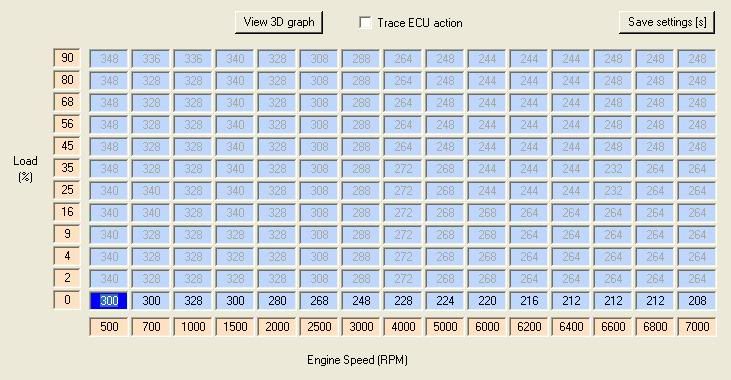
As far as I'm aware it doesn't use a cam signal but it does have a injection timing table. Ciaran, can you post up a screenshot of that please? Might be able to give you a few pointers to get your afrs closer until you get it on the RR Injection Timing 
I presume this is in degrees of crank rotation? |
||||||
|
96 Posts Member #: 7325 Advanced Member |
29th Jun, 2011 at 08:50:01pm
Im going to pull the plugs out as that will give an idea of whats going on and will discount a sensor or air leak issue.
|
||||||
|
1267 Posts Member #: 831 Post Whore Montreal, Canada |
29th Jun, 2011 at 09:02:13pm
On 29th Jun, 2011 ciaran said:
It doesnt use any cam sensor, AFAIK its to do with the ignition timing, I cant find out much as its got a Patent pending on it, Im not sure of the number but I have it in my thesis, Ill dig it out tomorrow. Actually, a patent makes it completely public. It just means you can't use the knowledge to make money on it without the agreement of the patent holder. And the Canems patent, at least the one I've seen references to, is actually taking what Marcel Chichak wrote many years ago on his web site so I don't see how this could be enforced but I may be wrong. In any case, it's quite simple (once you've figured it out) and simply fires an injector once per rev on each intake port using the same timing and pulse width. So while this is very simple to implement and does not require a cam sensor, it also can't deal with the different fuel requirements for the inner and outer cylinders. And the requirements are significantly different as Paul has shown in his initial tests. Jean |
||||||
|
96 Posts Member #: 7325 Advanced Member |
29th Jun, 2011 at 09:03:37pm
On 29th Jun, 2011 sturgeo said:
Edit: also how are you finding the mikunis? I'll most likely be running them on my na engine the mikunis are good, I took awhile to get the engine Idling right as I had a few air leaks, but I sorted them, The best thing about them so far is the noise, its unreal. I cant really comment about their performance till I let the engine have so high revs. I worked out that they were sufficient to flow enough air. However, I was told to go abit higher in the diameter, but I decided to stick with my calculations. |
||||||
|
96 Posts Member #: 7325 Advanced Member |
29th Jun, 2011 at 09:09:24pm
On 29th Jun, 2011 jbelanger said:
Actually, a patent makes it completely public. It just means you can't use the knowledge to make money on it without the agreement of the patent holder. And the Canems patent, at least the one I've seen references to, is actually taking what Marcel Chichak wrote many years ago on his web site so I don't see how this could be enforced but I may be wrong. Thats what I was thinking but I couldnt find anything on it patentwise, I did find the patent for the MPI solution, I have it in PDF if anybody wants to read it. On 29th Jun, 2011 jbelanger said:
In any case, it's quite simple (once you've figured it out) and simply fires an injector once per rev on each intake port using the same timing and pulse width. So while this is very simple to implement and does not require a cam sensor, it also can't deal with the different fuel requirements for the inner and outer cylinders. And the requirements are significantly different as Paul has shown in his initial tests. So, it would be very difficult or impossible to for the approach canems use to eliminate charge robbing? or even reduce it? Their claims are fairly impressive to be honest. |
||||||
|
857 Posts Member #: 1778 Post Whore Northants |
29th Jun, 2011 at 09:11:28pm
If you haven't already, have a good read of this: http://www.canems.co.uk/siameseports.php
|
||||||
|
857 Posts Member #: 1778 Post Whore Northants |
29th Jun, 2011 at 09:18:28pm
I personally believe that the canems system can be made to work better than a carb. We personally didn't have much luck with this method but with time working on your injection timing table and on a RR at various rpm/load sites you should be able to do a better job. It'll be better than any wet manifold setup which are about as good as pissing into the wind. |
||||||
|
96 Posts Member #: 7325 Advanced Member |
29th Jun, 2011 at 09:23:02pm
On 29th Jun, 2011 sturgeo said:
If you haven't already, have a good read of this: http://www.canems.co.uk/siameseports.php Ideally you'll want a rolling road that will let you play with your injection timing, most operators only do ignition and ve tables. Seems odd that the numbers appear to be grayed out on the table you posted, I might try and get hold of the software and have a look at it. Yea you can only change the timing at no load which is odd. |
||||||
|
96 Posts Member #: 7325 Advanced Member |
29th Jun, 2011 at 09:24:50pm
On 29th Jun, 2011 sturgeo said:
I personally believe that the canems system can be made to work better than a carb. We personally didn't have much luck with this method but with time working on your injection timing table and on a RR at various rpm/load sites you should be able to do a better job. It'll be better than any wet manifold setup which are about as good as pissing into the wind. Its semi wet if that makes any sense! the manifold is small but the injectore are upstream, its maybe 10cm from injector to valve. |
||||||
|
857 Posts Member #: 1778 Post Whore Northants |
29th Jun, 2011 at 09:37:19pm
http://www.canems.co.uk/pdf/injection_manual.pdf
|
||||||
| Home > A-Series EFI / Injection > Canems ECU 1380 N/A | |||||||
|
|||||||
| Page: |


