Donations towards server fund so far this month.

 
£0.00 / £100.00 per month
Page:
Home > A-Series EFI / Injection > DC Motor Control from ECU ???

Paul S

User Avatar

8604 Posts
Member #: 573
Formerly Axel

Podland

Next job is to build up the MS3/3X and run a simple test to see how the motor responds under no load.

That would be it until I can get the car on the road, but at the current rate of progress, that could be another year or so.

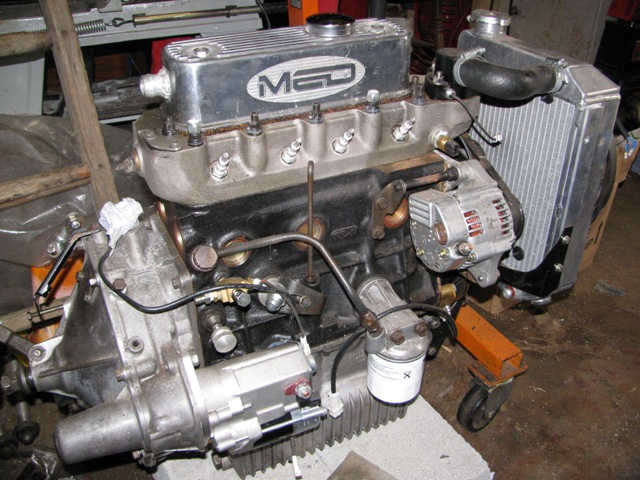
However, I keep tripping over this engine also waiting for love-struck son no. 1 to put in his car that is also currently in bits:


It occurred to me that I could actually do a load test with this to determine the pump characteristic and efficiency. Preliminary thoughts are to get a couple of large clear plastic containers with an interconnecting pipe and isolating valve. Connect them to the radiator outlet and pump inlet in place of the bottom hose.

For instrumentation, use the MS3 map sensor for discharge pressure. Put a pressure tapping in the core plug nearest the pump. Need to make a buffer of some kind to stop water getting in the sensor.

Hall sensor on a water pump bolt to read pump speed. Input into MS3 on one of the VSS channels.

Derive input power from volts and duty cycle?

Do a drop down test to measure flowrate at different speeds. That way we can observe the incidence of failure of suction performance at low temperature/head conditions that can be extrapolated empirically to normal operating conditions.

I would need a selection of dummy thermostats to give a range of discharge conditions. Also change the radiator to a 2 core one to get better simulation of normal head loss conditions.

Any thoughts? Anything I've overlooked?

Saul Bellow - "A great deal of intelligence can be invested in ignorance when the need for illusion is deep."
Stephen Hawking - "The greatest enemy of knowledge is not ignorance, it is the illusion of knowledge."


Rod S

User Avatar

5988 Posts
Member #: 2024
Formally Retired

Rural Suffolk

Just my initial thoughts.

Let's start with the hardest one first...
"Derive input power from volts and duty cycle? "

Although I originally suggested it, in the cold light of day, it isn't that easy. Input power is actually voltage x current (when it is flowing) x duty cycle.

And that assumes the current actually makes a nice square wave (matching the PWM drive signal) which isn't 100% true as the windings will have some inductance, but let's assume the inductance is low enough to ignore.

Now we can't assume the "on" current based on full motor power as it's 99% certain to be a series wound motor where there is a distinct relationship between current and torque.

So how to measure current, but only the "on" current...
A normal high current ammeter will tend to average the measured current over the on/off cycle because all they have inside them is a high power, low value, shunt resistor and actually measure the voltage drop (which will be averaged) and convert it to Amps. I'm not sure how the clip-on type work with DC (my speciallity is AC) but I'm sure they also average things.
But if you want to log this, you don't want ammeters and things, you want something to connect to the MS3 etc.

According to the specs (I don't know for sure as I don't use one) the MS3/X has three spare ADC inputs. Are these all available to you or do you have some designated for something else ?

Or do you still have your IOx board from back in your MS2 days ? (that has lots more).

Because, ignoring motor power for the moment, I would suggest you (a) shouldn't risk the MS3 MAP sensor and (b) you really need more than one. Two if you want to measure pump performance if you want a restriction (like a thermostat) in the system as an open flow test isn't open if you restrict it with a thermostat and the radiator is another restriction. And the only reason for not measuring the pump suction head would be if your water bottles are at such a height that you can be certain pump suction is atmospheric, otherwise I'd say three.

You might also want to measure more than one temperature, although I assume you intend to do this without the engine running (hence your thought of using the MS3's MAP port).

Rather than any fancy isolator to keep the water out of the MAP sensor, I would just get some more and mount "them" high above the engine connected by clear plastic tube running vertically, make sure you have good blue antifreeze (or just use food colouring if you want to test with plain water) and bleed the tubes so there is a 100-150mm pocket of air below the sensor. So long as the tube is a good sealed fit on the MAP sensor, the air pocket will protect it.

In the bigger picture of these projects, the MAP sensors are "cheap" but I wouldn't want the risk of having to replace the one on the mainboard. I'm not sure it would actually be killed by water, the datasheet says "Media, other than dry air, may have adverse effects on sensor performance and long-term reliability." not that it is instant death, but I wouldn't want water vapour left inside one. I've got PCBs to mount them on (Graham and mine's long term project to measure pressure, temperature, MAF around the air side) as you can't really use veroboard as they are not on a 1/10" pitch.

So that really only leaves how to measure motor instantaneous current.... (in a form suitable for an ADC input). Battery voltage and water temperature at one point is obviously available from the MS3.

I'm still thinking about motor current...

Schrödinger's cat - so which one am I ???


Paul S

User Avatar

8604 Posts
Member #: 573
Formerly Axel

Podland

Ha, just logged on to say that amps is going to be a problem to measure, even though I had not anticipated how big a problem.

I was planning on assuming a suction head based on tank elevation rather than measuring it. It should be easy to check and allow for suction losses once the flow rate is known.

The engine would not be running. Just drive the MS3 from a Jimstim. No real need for any temperature measurement. The test would not run for long enough for any of the water to get above ambient.

I do still have my IOX with 4 MAP sensors fitted, so I could risk one of them I suppose rather than the mainboard MAP sensor. Got to setup the CAN though.....pain.

It's not the end of the world if I cannot measure the power as this is really about hydraulics and thermodynamics. But it would complete the picture if we could.

Edited by Paul S on 18th Nov, 2013.

Saul Bellow - "A great deal of intelligence can be invested in ignorance when the need for illusion is deep."
Stephen Hawking - "The greatest enemy of knowledge is not ignorance, it is the illusion of knowledge."


stevieturbo

3588 Posts
Member #: 655
Post Whore

Northern Ireland

current monitoring...not that hard. There are hall sensors like these available that operate off 5v, and will let you log current via 0-5v on the ecu

the one in the link below is powered via 8v, you can get lots of different ones

http://www.scienceshareware.com/how-to-mea...fect-clamp-.htm

9.85 @ 145mph
202mph standing mile
speed didn't kill me, but taxation probably will


Rod S

User Avatar

5988 Posts
Member #: 2024
Formally Retired

Rural Suffolk

Intriguing Stevie, I allways thought Hall (or any magnetic field derived measurement) was AC only.

Still, never too old to learn.

The problem with the ECU reading it to log it is that the sample rate of the data logging will be so much lower than the PWM frequency, the log, at any given PWM percentage, will contain a mixture of zero values and the actual current value.

Not a problem to analyse the log manually after the event and use all the identical, non-zero, values to multiply by voltage and PWM percentage but it doesn't immediately lend itself to creating a "real time" power figure.

Perhaps forcing the output of the current measuring device to be an average (something as simple as a capacitor perhaps ?) and then just recording voltage x average current and ignoring the PWM part of the equation.

Or it "might" be possible to write a custom ini file to use the non-zero values only, although there's bound to be a few rogue values when the data is sampled just as PWM switches from on to off or vice versa.

Schrödinger's cat - so which one am I ???


Paul S

User Avatar

8604 Posts
Member #: 573
Formerly Axel

Podland

With the purpose of the test to be to establish the pump performance characteristics, it would probably be easier to bypass the PWM speed control.

A couple of big resistors would give three speeds if I use the full 12 volts as well. Alternatively I could use an old rheostat. Then we could use the hall effect current sensor that stevie identified.

Saul Bellow - "A great deal of intelligence can be invested in ignorance when the need for illusion is deep."
Stephen Hawking - "The greatest enemy of knowledge is not ignorance, it is the illusion of knowledge."


Rod S

User Avatar

5988 Posts
Member #: 2024
Formally Retired

Rural Suffolk

Sounds like a plan....

Measure the voltage across the motor itself and make sure the resistors are high power ones (back in my model engineering days before I changed to PWM I used to make my own) and one of those sensors anywhere in the circuit.

I had a quick look at Farnell's catalogue and they are not a bad price but, as Stevie says, there are others with different supply voltages and different current ranges readily available.

Schrödinger's cat - so which one am I ???


Paul S

User Avatar

8604 Posts
Member #: 573
Formerly Axel

Podland

One of these:

http://www.ebay.co.uk/itm/Vishay-Sfernice-...t-/150669698586

Totally confused by ratings for resistors :(

Saul Bellow - "A great deal of intelligence can be invested in ignorance when the need for illusion is deep."
Stephen Hawking - "The greatest enemy of knowledge is not ignorance, it is the illusion of knowledge."


stevieturbo

3588 Posts
Member #: 655
Post Whore

Northern Ireland


On 19th Nov, 2013 Rod S said:
Intriguing Stevie, I allways thought Hall (or any magnetic field derived measurement) was AC only.

Still, never too old to learn.

The problem with the ECU reading it to log it is that the sample rate of the data logging will be so much lower than the PWM frequency, the log, at any given PWM percentage, will contain a mixture of zero values and the actual current value.

Not a problem to analyse the log manually after the event and use all the identical, non-zero, values to multiply by voltage and PWM percentage but it doesn't immediately lend itself to creating a "real time" power figure.

Perhaps forcing the output of the current measuring device to be an average (something as simple as a capacitor perhaps ?) and then just recording voltage x average current and ignoring the PWM part of the equation.

Or it "might" be possible to write a custom ini file to use the non-zero values only, although there's bound to be a few rogue values when the data is sampled just as PWM switches from on to off or vice versa.


You'd still see an average current, or enough to be usable depending on how fast your logging rate is.
With a scope logging at a very high rate, you see lots of information

It's basically a more fixed version of these ( cheaper alternatives available on egay ) that you'd use with a meter or oscilloscope.
Thee run off a 9v battery, and output 0-5v based on current.

http://accessories.picotech.com/current-clamps.html

9.85 @ 145mph
202mph standing mile
speed didn't kill me, but taxation probably will


Paul S

User Avatar

8604 Posts
Member #: 573
Formerly Axel

Podland

I have a 2000A Heme Power Clamp. I used to use it professionally until I nearly killed myself trying to use it in a live 200kW starter :(

It has a 0-40A minimum current range. It can also measure volts and Watts and has an RMS setting. Unfortunately it does not have a logging facility.

Saul Bellow - "A great deal of intelligence can be invested in ignorance when the need for illusion is deep."
Stephen Hawking - "The greatest enemy of knowledge is not ignorance, it is the illusion of knowledge."


stevieturbo

3588 Posts
Member #: 655
Post Whore

Northern Ireland

If you wanted a current clamp for workshop use and for temporary logging with the ecu, this is what I bought to use with the USB scope

http://www.ebay.co.uk/itm/Hantek-CC-65-AC-...=item3a8202e9d5

Just a cheaper version of what Pico sell, although this one has a BNC plug.

Takes a 9v battery and outputs based on current.


So whilst it says 60A, it should do a lot more, although Ive only used it to a 30A range or so so far.

9.85 @ 145mph
202mph standing mile
speed didn't kill me, but taxation probably will


Rod S

User Avatar

5988 Posts
Member #: 2024
Formally Retired

Rural Suffolk

On 19th Nov, 2013 Paul S said:
Totally confused by ratings for resistors :(


Before the long boring bit, if you don't want to make your own resistor(s) - it's really quite easy, as I'll say later - I think you would be better of using your PWM drive and any of the current measuring devices suggested - you need to test it anyway ???


So for resistor(s)...

OK, a bit simplistic, but let's say the motor maximum rating is 1KW.

From P=VI That's 83A at 12V

So you want to run at 1/2 speed and simplistically say by dropping the motor voltage to 6V using a resistor, firstly the resistor should be the same value as the motor windings (which it's allways difficult to be precise about because of inductance and back EMF in DC motors) in which case the total circuit resistance doubles so the Amps halve (42A). Because the voltage across the motor has also halved, this means the motor is now at 1/4 power.

If motor resistance was as simple as V=IR the resistance of a 1KW, 12V motor would be 0.15Ohms so you would need a 0.15Ohm resistor in series to achieve this. The resistor rating would need to be 250W because you have split the 12V into two 6V parts of the potential divider at half the overall current (so P=6x42 or you can use P=I^2R so 42^2x0.15, both give the same, subject to rounding errors).

But if you don't want the motor to run so slow, let's say you want 9V across the motor, the resistor would need to go down to 0.05hms - simple potential divider - 9/12 = (0.2/(0.15+0.05))
Total resistance is now 0.2Ohm so total current (I=V/R) is 60A
And by I^2R, the resistor now has to disipate 180W and the motor 540W


That's why PWM is the only sensible way to drive a DC motor to avoid wasted heat.

But if you want to try resistor(s) you are looking at a ball park figure of 0.05Ohms to 0.25Ohms

The problem is compounded though with a variable resistor like the one you have linked (ignoring the fact it's to high a value for the moment).
Although it is 600W, that type of resistor will only be able to disipate 600w when the whole of the length is in use, ie, it's maximum resistance.
Once you move the slider to half way down it will only be able to dissipate 300W without the half that is in use overheating. Use even less and it gets worse.

So although the drop in power of the resistor goes down slightly as per my example above, it isn't linear like the slider type variable resistors.

Better to use individual resistors of different values to test at individual speed/power if you want to use resistors.

But you are not likely to find such low values (Ohms) at such high powers off the shelf.

What I did in my model engineering days (before I went PWM) was make my own.

I'll describe how later if you want to do it (maybe even find one of my old ones and photo it) but if I say now, someone will take the piss...

Schrödinger's cat - so which one am I ???


Paul S

User Avatar

8604 Posts
Member #: 573
Formerly Axel

Podland

Ummm, we'll see.

I wonder if there is a way that I can calibrate my power clamp to the PWM signal .......... *Idea*

Anyway, I've just got the dodgy old MS2 reconfigured with the MS3 processor and talking to TunerStudio :)

Next job is to get it all in a case withe the MS3X and wire up a test circuit for the motor and controller.

Saul Bellow - "A great deal of intelligence can be invested in ignorance when the need for illusion is deep."
Stephen Hawking - "The greatest enemy of knowledge is not ignorance, it is the illusion of knowledge."


Paul S

User Avatar

8604 Posts
Member #: 573
Formerly Axel

Podland

Well that was a great success........... not. The smell of electrical burning has filled the house.

The circuit did not do as intended or I did not build it right. Hooked it all up and it melted the transistor :(

TS said that it was outputting a PWM signal but I could not measure any drop across the transistor. Thought it might have been the meter, so hooked it up anyway.

Whilst I had it setup I gave the motor full 12 volts. A 30 amp cable nearly melted at no load :(

Fook.

Saul Bellow - "A great deal of intelligence can be invested in ignorance when the need for illusion is deep."
Stephen Hawking - "The greatest enemy of knowledge is not ignorance, it is the illusion of knowledge."


stevieturbo

3588 Posts
Member #: 655
Post Whore

Northern Ireland

no fuse ?

Even for starters. With no load on the motor, current draw should be fairly small.

9.85 @ 145mph
202mph standing mile
speed didn't kill me, but taxation probably will


Rod S

User Avatar

5988 Posts
Member #: 2024
Formally Retired

Rural Suffolk

That does seem a bit strange.

Have you got photos of both sides of the board in case it's something obvious ?

As Stevie says, the current at no load should be really small. That's the nature of series wound DC motors (which yours 99% certain will be), they only draw current when they slow down to produce torque.

Un-loaded their current draw is only determined by their internal bearing friction and windage as, mathematically, they over-speed at minimal current when unloaded.

Schrödinger's cat - so which one am I ???


Joe C

User Avatar

12307 Posts
Member #: 565
Carlos Fandango

Burnham-on-Crouch, Essex


erm, should there not be a pull down on the gate of the Mosfet?

also whenever I build a circuit like this I test it on a small resistive load first, as chances are If Ive built it, it will go bang first time!

Also mosfets can be fussy buggers, static spike up the gate can easily kill them,


http://www.sturgess.plus.com/jas//New%20Ph...Controller3.jpg

On 28th Aug, 2011 Kean said:
At the risk of being sigged...

Joe, do you have a photo of your tool?


http://www.turbominis.co.uk/forums/index.p...9064&lastpost=1

https://joe1977.imgbb.com/


Paul S

User Avatar

8604 Posts
Member #: 573
Formerly Axel

Podland

Well, the motor nearly jumped off the bench when I applied 12v. Too much torque and a huge amp draw to go with it.

Notwithstanding the motor current issue, the circuit was not firing the mosfet. Something is missing, as Joe says.

I'm going to replace the burnt out mosfet and fire it up against a headlight bulb next time.

Can I use the Jimstim to test the PWM output? Connect the output wire through an LED to 12v?

Also, does the PNP transistor mean that the duty cycle is inverted?

Saul Bellow - "A great deal of intelligence can be invested in ignorance when the need for illusion is deep."
Stephen Hawking - "The greatest enemy of knowledge is not ignorance, it is the illusion of knowledge."


Joe C

User Avatar

12307 Posts
Member #: 565
Carlos Fandango

Burnham-on-Crouch, Essex


Paul,

Ive just whacked some values into a simulator and had a play,

simulator app....

http://www.falstad.com/circuit/


circuit on....


circuit off


On 28th Aug, 2011 Kean said:
At the risk of being sigged...

Joe, do you have a photo of your tool?


http://www.turbominis.co.uk/forums/index.p...9064&lastpost=1

https://joe1977.imgbb.com/


Joe C

User Avatar

12307 Posts
Member #: 565
Carlos Fandango

Burnham-on-Crouch, Essex

essentially you need a pullup on the gate to turn the Fet off otherwise it'll shit itself.

On 28th Aug, 2011 Kean said:
At the risk of being sigged...

Joe, do you have a photo of your tool?


http://www.turbominis.co.uk/forums/index.p...9064&lastpost=1

https://joe1977.imgbb.com/


Paul S

User Avatar

8604 Posts
Member #: 573
Formerly Axel

Podland

Thanks Joe.

However, the MS3X outputs are ground switching rather than 12v.

Saul Bellow - "A great deal of intelligence can be invested in ignorance when the need for illusion is deep."
Stephen Hawking - "The greatest enemy of knowledge is not ignorance, it is the illusion of knowledge."


Joe C

User Avatar

12307 Posts
Member #: 565
Carlos Fandango

Burnham-on-Crouch, Essex

just stick another NPN transistor stage on the front end to invert it?

On 28th Aug, 2011 Kean said:
At the risk of being sigged...

Joe, do you have a photo of your tool?


http://www.turbominis.co.uk/forums/index.p...9064&lastpost=1

https://joe1977.imgbb.com/


Paul S

User Avatar

8604 Posts
Member #: 573
Formerly Axel

Podland

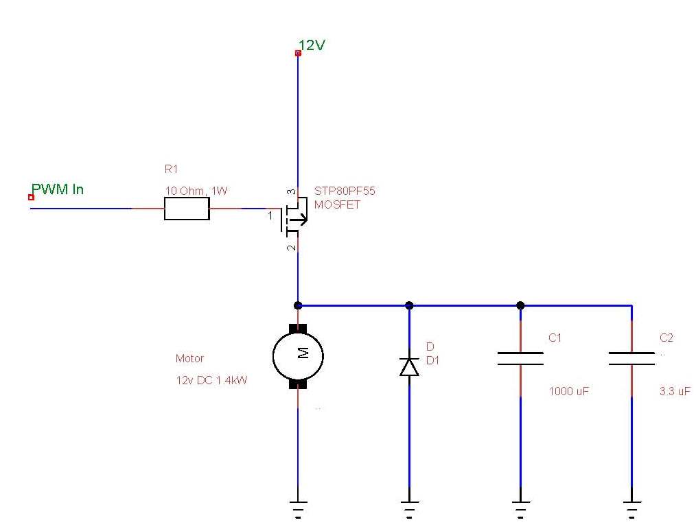
Let's be clear. this is the circuit that I'm currently using:

Saul Bellow - "A great deal of intelligence can be invested in ignorance when the need for illusion is deep."
Stephen Hawking - "The greatest enemy of knowledge is not ignorance, it is the illusion of knowledge."


Joe C

User Avatar

12307 Posts
Member #: 565
Carlos Fandango

Burnham-on-Crouch, Essex

Ah ok,

I thought you was using the circut with the transistor at the front.

in that case you just need a resistor between pins 1 & 3 of the fet to pull the gate up to 12v to turn it off, then the MS will mull it down to turn on,

dunno what you've got in the MS driving this but you'll need to consider the current, whta can the MS support? in terms of turning the fet on its next to F all I'd go with a 10k between pins 1&2 and a 1 k out to the MS,

I would try the circuit without the MS to, stick a pot from the PWM above to gnd and see if you can control a lamp ect, then try it on the motor.

On 28th Aug, 2011 Kean said:
At the risk of being sigged...

Joe, do you have a photo of your tool?


http://www.turbominis.co.uk/forums/index.p...9064&lastpost=1

https://joe1977.imgbb.com/


Paul S

User Avatar

8604 Posts
Member #: 573
Formerly Axel

Podland

I agree with you Joe. I can't see how it would switch without some volts on the gate.

What you propose will invert the duty rating..... I think ?????

What sort of watt rating will I need on these resistors?

The solid state relay option looks very appealing.

I still need to check the output of the MS3X.

Edited by Paul S on 24th Nov, 2013.

Saul Bellow - "A great deal of intelligence can be invested in ignorance when the need for illusion is deep."
Stephen Hawking - "The greatest enemy of knowledge is not ignorance, it is the illusion of knowledge."

Home > A-Series EFI / Injection > DC Motor Control from ECU ???
Users viewing this thread: none. (+ 2 Guests) <- Prev   Next ->
To post messages you must be logged in!
Username: Password:
Page: