Donations towards server fund so far this month.

 
£0.00 / £100.00 per month
Page:
Home > Show Us Yours! > Project "Marginal gains..."

Aubrey_Boy

User Avatar

690 Posts
Member #: 9962
Post Whore

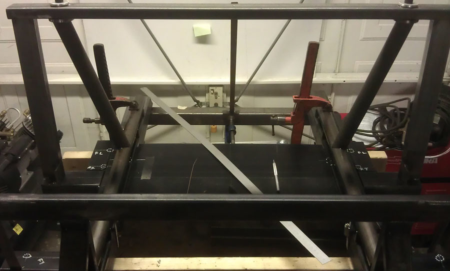
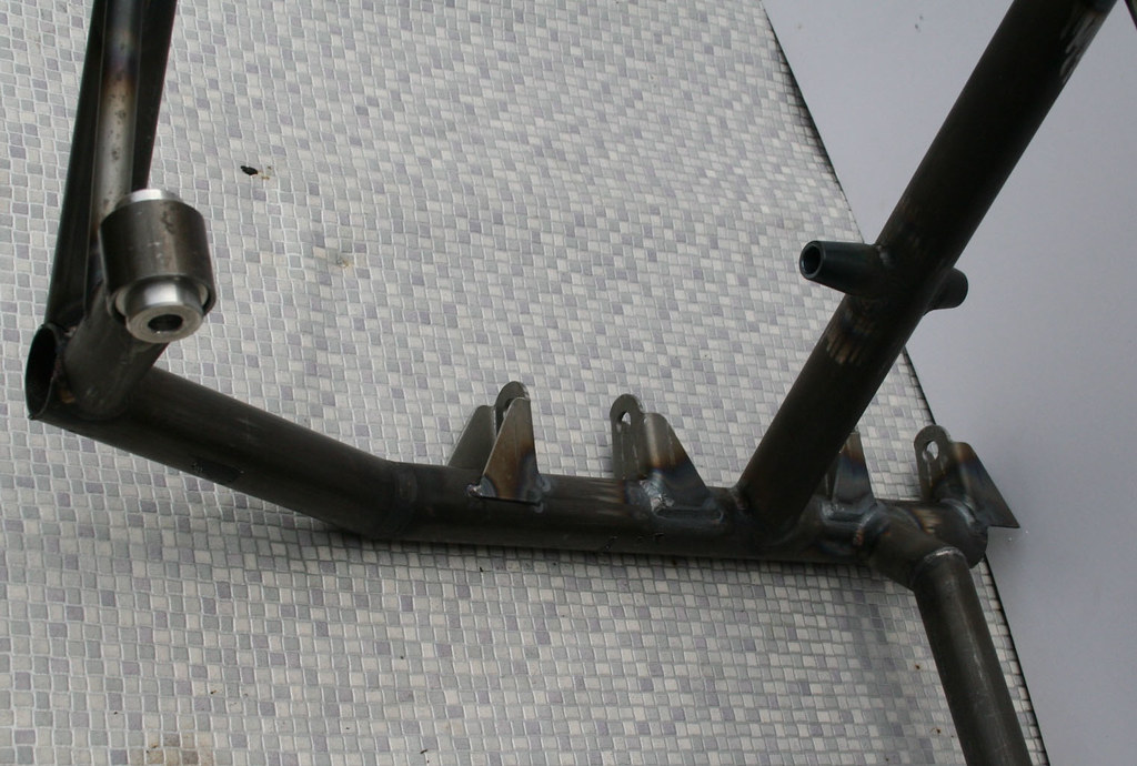
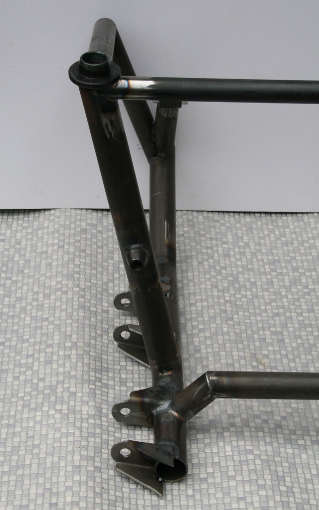
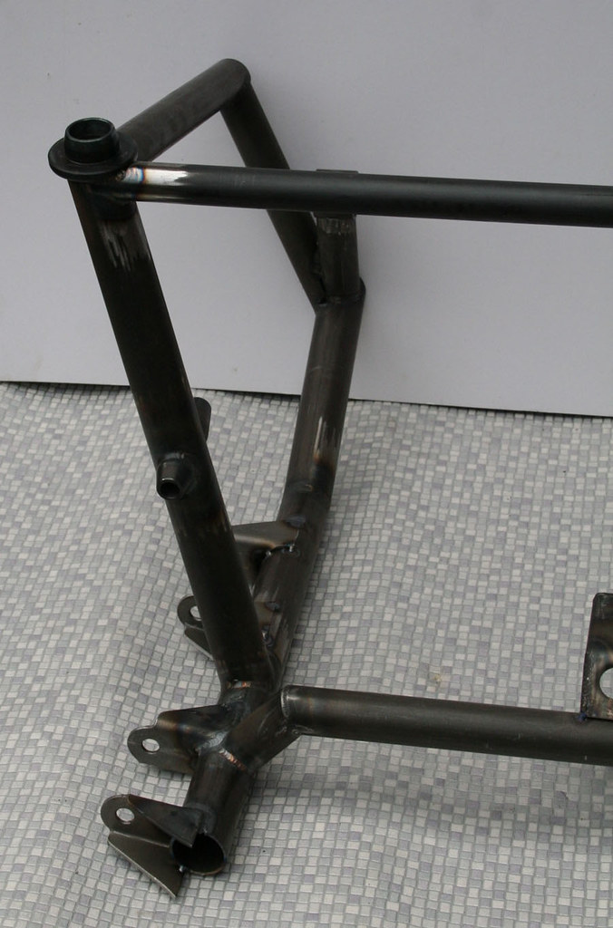
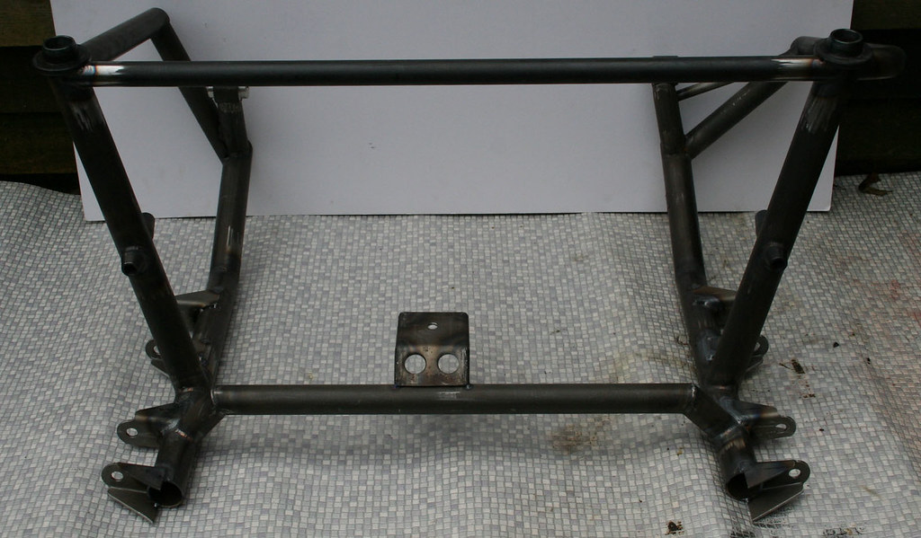
A bit more done, it's taking ages because there is so little space each time you change something you have to fully mock up everything in that area as some many things are within a few mm

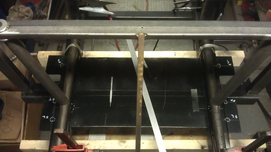
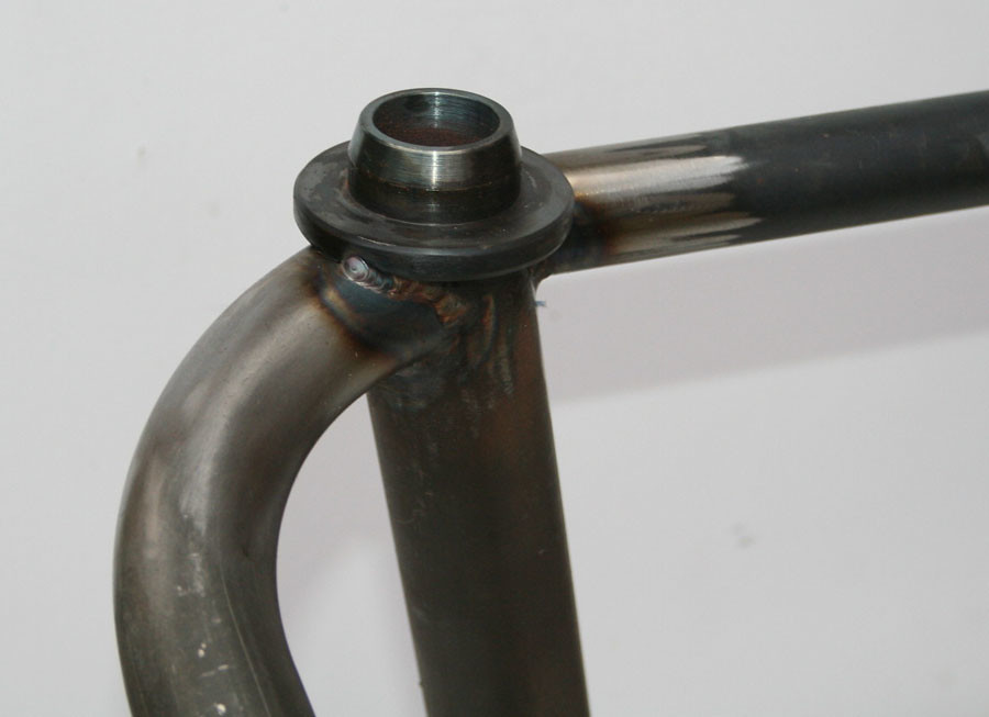
The main vertical part of the frame which will also take the top wishbone rear mounts:


The vertical legs are angled back in order to clear the inner CV joints which are one of the many obstructions which prevent the engine / gearbox from moving back


Cheers

Edited by Aubrey_Boy on 7th Jul, 2017.


madmk1

User Avatar

5417 Posts
Member #: 6181
Double hard bastard

brookwood woking

Looks good mate. that is what put me off making a frame. making a frame to make the frame in *hehe!*

I have started posting on Instagram also my name on there is turbomk1golf

Nothing is impossible it just costs more and takes longer.

On 1st Nov, 2007 Ben H said:
There is no such thing as 'insignificant weight saving', it all adds up.


Aubrey_Boy

User Avatar

690 Posts
Member #: 9962
Post Whore

Cheers, yes even with the 'jig' it is still suprising how much things can move if you weld one area too much before welding elsewhere

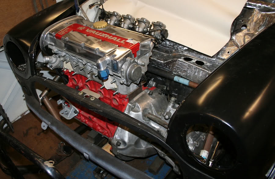
Started the first mock up of the new subframe;

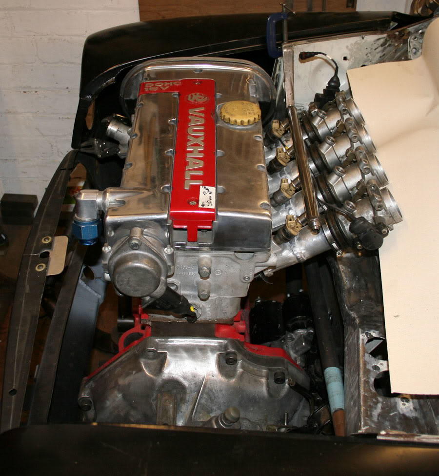
I think this will be the engines final resting position as it is a compromise between driveshaft angles, bonnet / wing clearance and the fact that the back of the cam belt cover is now only about 15mm from the rear bulkhead

You can also see I have stripped the entire bulkhead back to bare metal as I wasn't happy with the previous tidy up I had done, the seam sealer was a bit of a mess so I've had to dig all of that out too.


This shows the back of the cam belt to bulkhead clearance better, the starter motor is also closer than I was expecting


Cheers

Edited by Aubrey_Boy on 18th Oct, 2017.


Aubrey_Boy

User Avatar

690 Posts
Member #: 9962
Post Whore

The subframe is back in the jig having the upper wishbone mounts and the steering rack / cross member tube added.

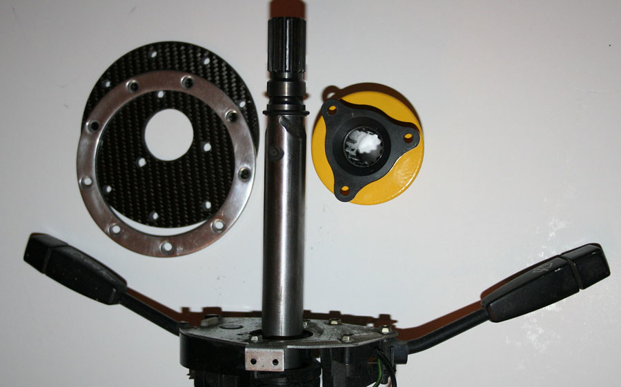
Other stuff which I can get on with which doesn't rely on the subframe being finished includes the steering column;

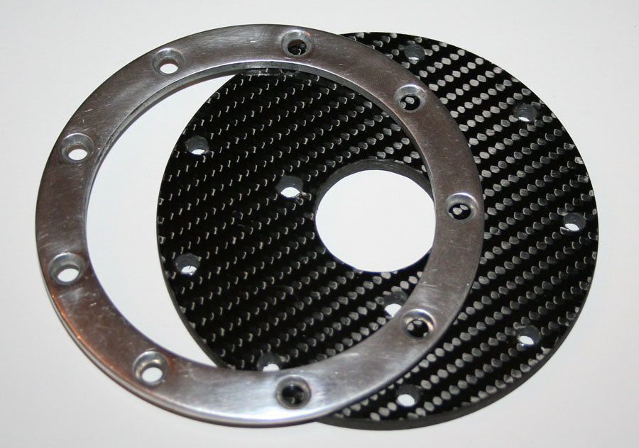
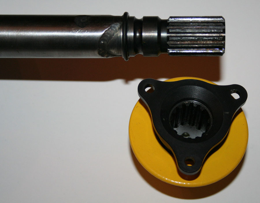
I have used a piece of 'structural' carbon fibre to make a steering boss adaptor to attach the Motolita steering wheel to the single seater type QR fitting (As no one seems to make this adaptor):


By 'structural' I just mean it has been properly autoclaved and is about 5mm thick pre preg.

The QR is a Laranca manufactured item and is in my opinion one of the best QR's at a sensible price, there is no noticeable backlash / play which seems to be a feature of many of the cheap QR's.


I am using the std column stalks and mountings so I can swap back to a completely standard column if required


Cheers

Edited by Aubrey_Boy on 18th Oct, 2017.


apbellamy

User Avatar

16540 Posts
Member #: 4241
King Gaycharger, butt plug dealer, Sheldon Cooper and a BAC but generally a niceish fella if you dont mind a northerner

Rotherham, South Yorkshire

Interesting. I'm in the middle of planning how to bastardise my wheel onto one of the lower end of the market QR adaptors. I am too tall for a mini...

On 11th Feb, 2015 robert said:
i tried putting soap on it , and heating it to brown , then slathered my new lube on it

*hehe!*


kcchan

264 Posts
Member #: 8853
Senior Member

Bristol

I bought a laranca one too, they're not as expensive as you think


Aubrey_Boy

User Avatar

690 Posts
Member #: 9962
Post Whore

For some reason the Laranca badged QR's seem to have disappeared off the face of the earth, SPA seems to have a very similar one... But I used the single seater one as it was both the cheapest and the lightest that they did. Demon Tweeks do one which is like my Laranca one but seems to have gone from a CNC profile to a straight edged design?

Cheers

Edited by Aubrey_Boy on 3rd Dec, 2014.


Aubrey_Boy

User Avatar

690 Posts
Member #: 9962
Post Whore

For one reason and another I am considering going with a hydraulic clutch

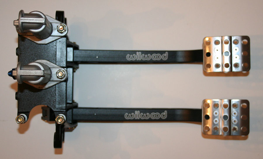
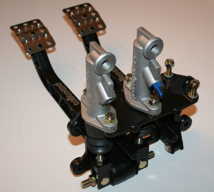
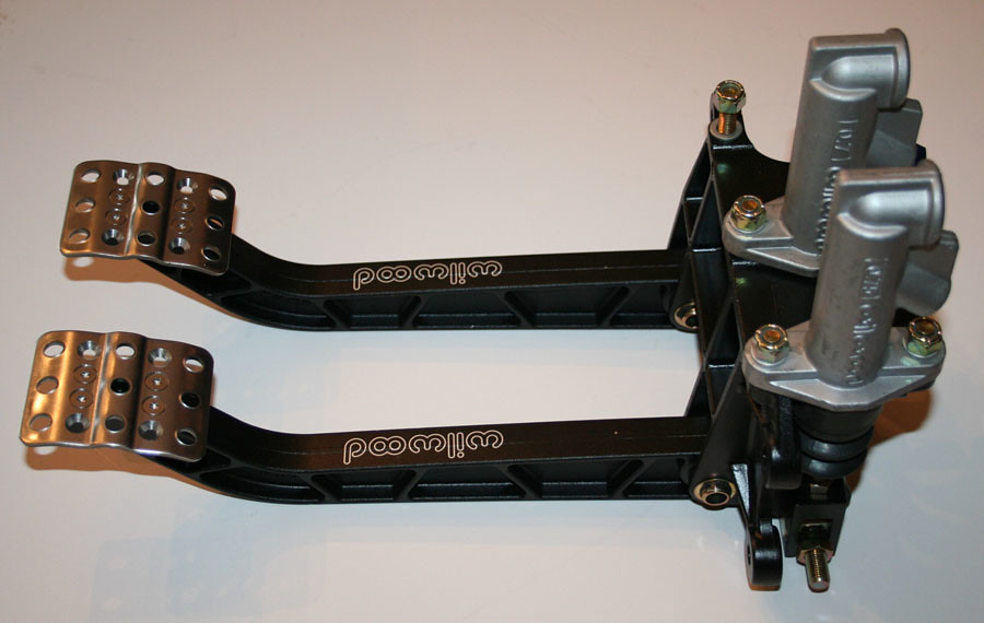
This is a pedal box I bought for my Midget project and I am considering using it this car to try and help with the pedal position and spacing as I damaged my right ankle some time ago and I think it's one of the areas that going back to driving a Mini may cause me problems

I looked at modifying the bias pedal box I have already made but just couldn't face cutting it up again so I took the easy route

It is the latest one they do, Part No. 340-11299

And here's a bit of a critique...

I think I have mentioned before but rightly or wrongly I am not a massive fan of Wilwood but the quality of this pedal box is OK. There is a bit of lateral movement in the in the fulcrum for both the brake and the clutch pedal which equates to about 3mm at pedal face.

So I took the pedal assemblies apart for a closer look to see if it is feasible to shim this movement.

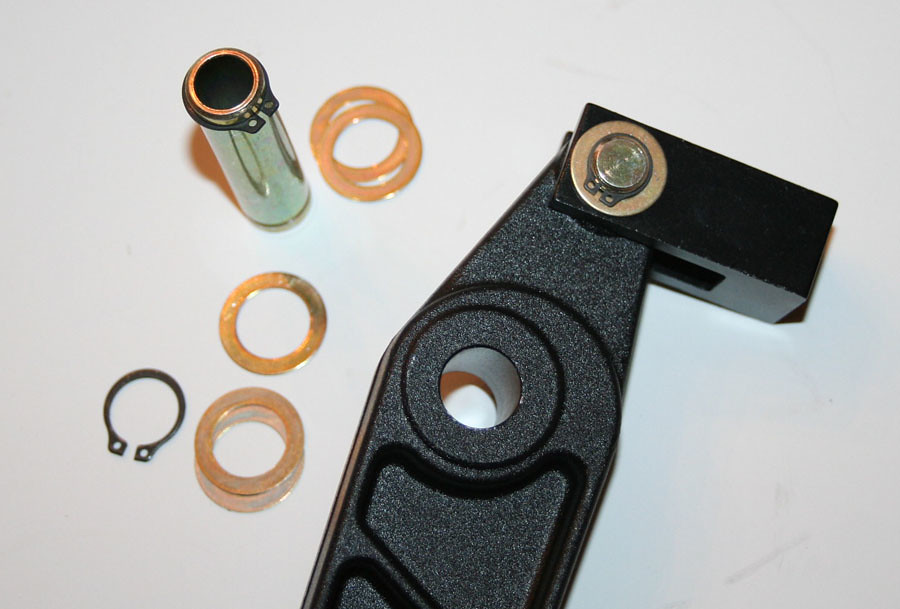
This is the clutch pedal but the brake pedal pivot is the same (I did take it apart too)


As you can see the pivot is a hollow tube with circlips either side, which I assume is done for weight saving (compared to a nut and bolt) and is a perfectly acceptable method of holding the pedal IMO.

I was however a little suprised to see no plain bearing at all, sure I didn't expect roller / thrust roller bearings but just a little suprised to see the pivot run directly into an aluminium machined casting. The washers you can see are all the same thickness - so I assume there is no attempt at shimming the lateral play out, the assembly was dry with no grease / lubricant (Again I took both pedal apart - both were bone dry).

The centre bore of both pedals have burrs from machining (clutch pedal slightly worse) which combined with the fact that the sides of the pedal in the area of the pivot are not spot faced / machined again would make properly shimming during assembly difficult.

The brake bias pivot is exactly the same as the unit I used in my steel pedal box - again no bearings plain or otherwise but OK for the cost of the item.

A few general views:


When I looked on the Wilwood website I noticed they don't quote a weight for this 'new' derivative compared to the older version which is 3.5 lbs (1.59 Kg) - I weighed it at 1.96 Kg so roughly 300 grammes heavier than the old one (Assuming the weight quoted for the older one is accurate). I have no experience of the previous pedal box so it could be that this unit has better stiffness / less flex compared to the old one which explains the weight increase.

The pedal pads weigh 100g each which felt very heavy but they have holes which allow them to have the pedal lateral position moved - so I think they are a bit heavier than they need to be to allow for this possible offset / bending.

I decided to write this critique because I have pondered for a few years now about buying such a pedal box rather than hacking around a std one - so I thought it might be of interest to others to see how they are made / what is used. Hopefully it is interesting / useful.

I have used and tested AP pedal boxes which are in the £1000's and have all the aforementioned roller bearings / expensive bias assemblies and I appreciate that these are made to a much lower price.

I still think that there is a gap in the market between Wilwood / OBP and say AP / Brembo / Alcon, if they did a 'Pro' version of this pedal box with plain bearings (which cost pennies) plus the additional cost of machining the sides of the pedals I would pay extra for it.

I am looking into what plain bearings which could be packaged into the assemblies but the material around the pivot bosses might mean this isn't feasible.

But overall I would buy this pedal box again, if I buy one for the Midget I will probably buy the older one which is £20 cheaper just to see the differences between the two, but I would recommend stripping it down, seeing if you can shim the lateral play and definately greasing the pivots...

Cheers

Edited by Aubrey_Boy on 18th Oct, 2017.


Aubrey_Boy

User Avatar

690 Posts
Member #: 9962
Post Whore

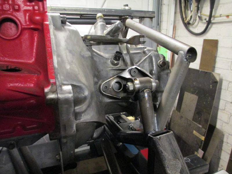
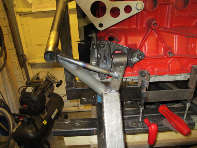
Its been a while, but the subframe is still progressing, albeit more slowly than I had hoped.

This is the LHF engine mount area, it's a not completely clear in the photo as the rectangular box section at the front is part of the jig


And this the RHF engine mount area


Still needs the both of the rear engine mounts to be done and the rack mounts added, then it will need putting back in the car to establish where the remoavable front lateral structure can be added and still fit inside a standard length front and ideally hide behind the front panel without being on show.

Cheers

Edited by Aubrey_Boy on 7th Jul, 2017.


matty

User Avatar

8297 Posts
Member #: 408
Turbo Love Palace Fool

Aylesbury

Superb, that subframe is really starting to take shape now!

https://www.facebook.com/pages/Fusion-Fabri..._homepage_panel

www.fusionfabs.co.uk


1/4mile in 13.2sec @ 111 terminal on 15psi


Rob Gavin

User Avatar

6729 Posts
Member #: 618
Post Whore

Glasgow

I can't believe i've missed this thread - excellent fab work going on


MarkGTT

User Avatar

3249 Posts
Member #: 1194
Post Whore

Shropshire.

thanks for the pedal box info, im looking at buying one for my vauxhall build.

Project looks great too - some impressive fabrication work.


cossierick

User Avatar

3074 Posts
Member #: 1348
Post Whore

wakefield West Yorks


On 28th Jan, 2013 Rob Gavin said:
I can't believe i've missed this thread - excellent fab work going on


Dito *happy**happy**happy*

looks awsome

rick


gr4h4m

User Avatar

4890 Posts
Member #: 1775
Post Whore

Chester

Very nice, got to love some welding action...

I run a supercharger and I don't care the TB is on the wrong side.
VEMS + 12 PSI + Liquid Intercooler = Small Bore FUN!


Aubrey_Boy

User Avatar

690 Posts
Member #: 9962
Post Whore

Thanks very much for the comments, hopefully by next week the subframe will be ready to trial fit in the car again - but this will just be to check engine position as I need to get the wishbones fabricated in order to do much else.

Cheers

Edited by Aubrey_Boy on 18th Oct, 2017.


kcchan

264 Posts
Member #: 8853
Senior Member

Bristol

Great work. Is the engine solid mounted or are the bushes a polymer of some sort?


Aubrey_Boy

User Avatar

690 Posts
Member #: 9962
Post Whore

Hi,

Thanks for the comments,

No not solid mounted, the bushes are metalastic, pretty stiff and only time will tell if they are too stiff.

I have placed spacers either side of each bush which gives a little laleral adjustment at this stage but will also allow me to convert to slightly bigger bushes if they are too agressive.

I don't like poly bushes for anything, suspension or otherwise.

Cheers

Edited by Aubrey_Boy on 29th Jan, 2013.


Aubrey_Boy

User Avatar

690 Posts
Member #: 9962
Post Whore

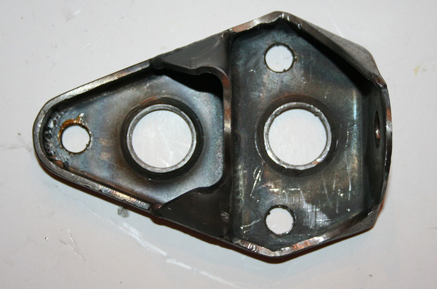
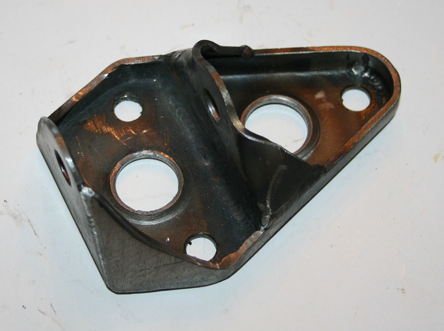
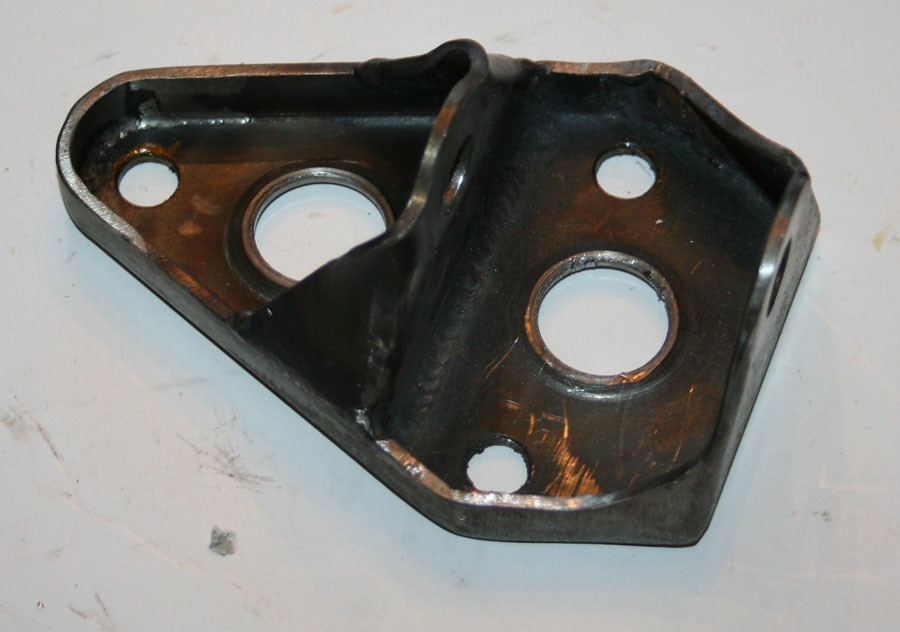
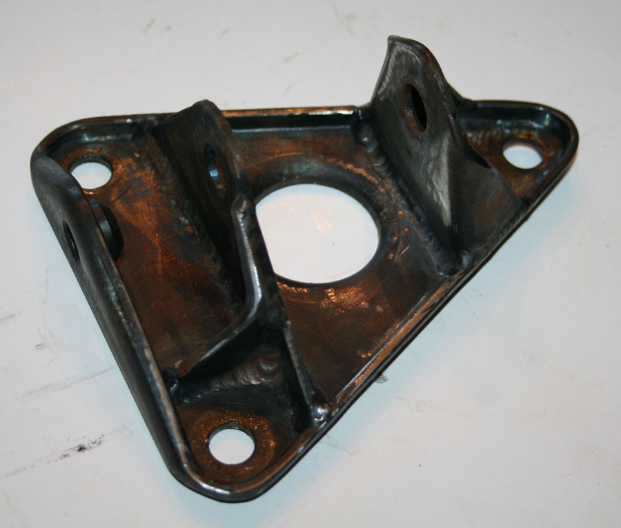
The front engine mounts are done now

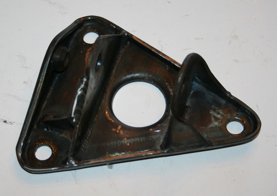
This is the gearbox mount, the mounts are 3mm S514 steel


This is the RH front mount, the threaded boss in the side is for the alternator tensioning link


They just need a bit of linishing but not sure on what finish to put on them yet

Cheers

Edited by Aubrey_Boy on 7th Jul, 2017.


Aubrey_Boy

User Avatar

690 Posts
Member #: 9962
Post Whore

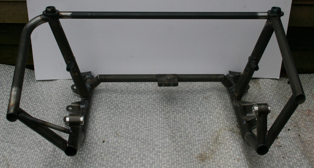
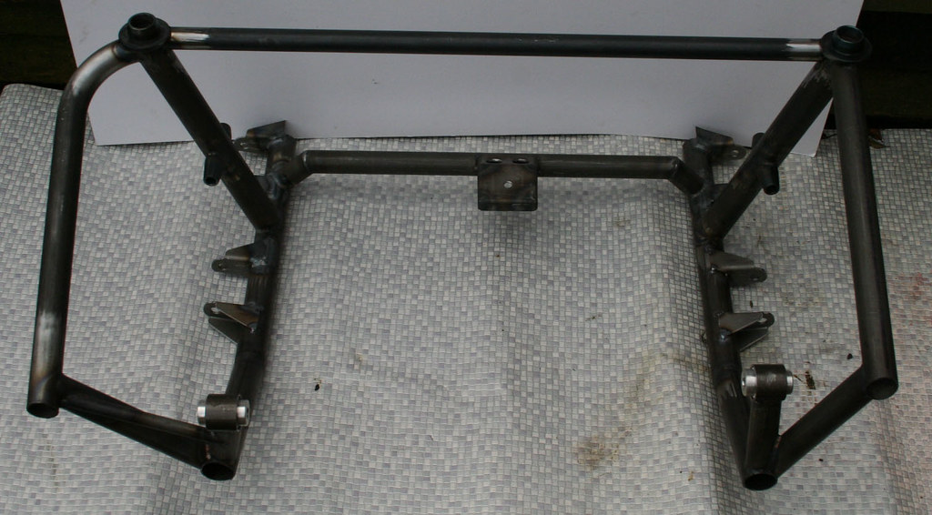
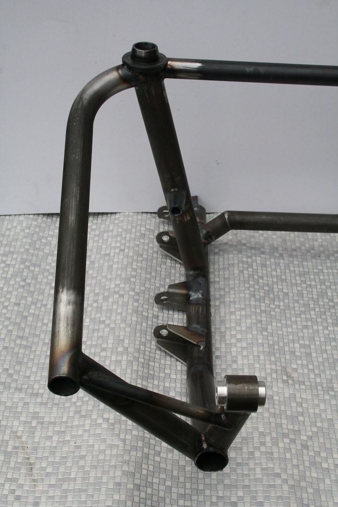
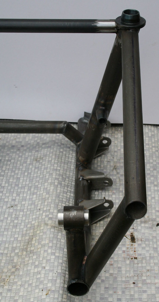
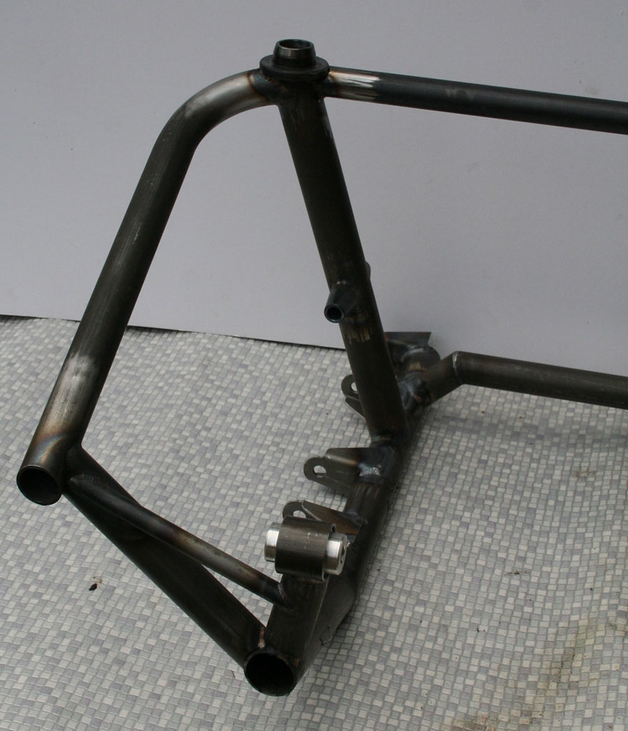
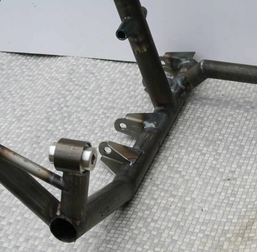
The subframe itself has progressed a bit, still not finished but time to fit to the car and check clearances again


All of the tubes are T45 now and the wishbone mounts and rear engine mount sheet metal are S514


The front engine mounts will be metalastic but they are turned ali at the moment whilst positioning everything

It currently weighs in at just over 8.5 kg but will no doubt creep just over 10 kg which was my original target maximum weight.


Currently has 3 mounts but I am trying to decide if / where to put a fourth anti rotation mount


Cheers

Edited by Aubrey_Boy on 7th Jul, 2017.


TomBooth

User Avatar

299 Posts
Member #: 2814
Senior Member

Mansfield - Notts

That's looking fantastic, looking foward to more of this build!


gr4h4m

User Avatar

4890 Posts
Member #: 1775
Post Whore

Chester

Looks very neat...

I run a supercharger and I don't care the TB is on the wrong side.
VEMS + 12 PSI + Liquid Intercooler = Small Bore FUN!


mercenary62

User Avatar

641 Posts
Member #: 9937
Post Whore

somewhereintheuniverse near selkirk scotland

very good description and pics mate keep them coming , im fitting a c16se engine in mine using an allspeed frame

give em hell


Aubrey_Boy

User Avatar

690 Posts
Member #: 9962
Post Whore

Thanks for the kind comments

mercenary62,

Thanks, do you have a build diary?

Cheers


Jay#2

User Avatar

2500 Posts
Member #: 648
Post Whore

Northern Ireland (ex AUS)

Top quality work, you must be a surgeon as a day job.

On 7th Nov, 2008 Nic said:
naeJ
m
!!!!!!sdrawkcab si gnihtyreve ?droabyekym ot deneppah sah tahw ayhwdd


Aubrey_Boy

User Avatar

690 Posts
Member #: 9962
Post Whore

Cheers Jay

Sadly I currently sit at a desk looking at a screen for a living, need to get out more

Cheers

Home > Show Us Yours! > Project "Marginal gains..."
Users viewing this thread: none. (+ 1 Guests) <- Prev   Next ->
To post messages you must be logged in!
Username: Password:
Page: