| Page: |
| Home > A-Series EFI / Injection > Inlet Manifold Design | |||||||
|
8604 Posts Member #: 573 Formerly Axel Podland |
30th May, 2007 at 07:31:43pm
On 30th of May, 2007 at 07:16pm robert said:
neat hole cutting and fab axel Best bit was when I set light to the work bench with the plasma cutter. Ensconced in my auto-darkening welding helmet, I didn't realise until I smelt the smoke. Ripped off the helmet to find my bench and a bag beneath alight. Luckily I had a watering can handy! I usually get Axel to fire watch when I'm cutting but he was not about. Saul Bellow - "A great deal of intelligence can be invested in ignorance when the need for illusion is deep."
|
||||||
|
2514 Posts Member #: 1217 I like nice quiet girly Minis Cheltenham, Gloucestershire |
30th May, 2007 at 07:35:12pm
LOL ..... once set fire to my overalls ... that I was wearing!!!! Autodarkening helmets are a god send and a bloody liability in similar measures!!!
Every day is a school day ...........
On 27th of Sep, 2007 at 12:45pm Jimster said:
why do you you think I got a girlfriend with small hands? |
||||||
|
Forum Mod 10980 Posts Member #: 17 ***16*** SouthPark, Colorado |
30th May, 2007 at 07:40:22pm
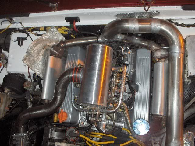
Why not stick the inlet to it in the middle of the runners? This is how mine is schemed out - I actually have a 2" dia 90-degree coming out of the front of the plenum tube, and the flange on the end for the TB. You end up with a lot more room this way - and uses the 'dead' space between plenum and rocker box.
On 17th Nov, 2014 Tom Fenton said:
Sorry to say My Herpes are no better Ready to feel Ancient ??? This is 26 years old as of 2022 https://youtu.be/YQQokcoOzeY |
||||||
|
8604 Posts Member #: 573 Formerly Axel Podland |
30th May, 2007 at 07:43:07pm
You're assuming that my welding skills will manage 1mm Saul Bellow - "A great deal of intelligence can be invested in ignorance when the need for illusion is deep."
|
||||||
 6748 Posts Member #: 828 Post Whore uranus |
30th May, 2007 at 08:04:03pm
yes dave thats whet i did on the tvr shown in a pic earlier ,but hey if its not giving a good mix distribution ,axel can do version 28 !! Medusa + injection = too much torque for the dyno ..https://youtu.be/qg5o0_tJxYM |
||||||
 4559 Posts Member #: 786 Post Whore Bermingum |
30th May, 2007 at 08:13:34pm
Hi,
VEMs Authorised Installer / Re-seller. K head kits now available!
|
||||||
|
8604 Posts Member #: 573 Formerly Axel Podland |
30th May, 2007 at 08:27:13pm
I think that the middle feed idea is very good.
Saul Bellow - "A great deal of intelligence can be invested in ignorance when the need for illusion is deep."
|
||||||
 6748 Posts Member #: 828 Post Whore uranus |
30th May, 2007 at 09:06:33pm
heres what i did on the tvr axel , interestingly , it does run slightly leaner on the far side cyl 1 and 2 due to the inertia of the flow biasing towards these two . Medusa + injection = too much torque for the dyno ..https://youtu.be/qg5o0_tJxYM |
||||||
|
8604 Posts Member #: 573 Formerly Axel Podland |
30th May, 2007 at 09:08:41pm
Did you get any problems due to the TB being a long way from the plenum? Saul Bellow - "A great deal of intelligence can be invested in ignorance when the need for illusion is deep."
|
||||||
 6748 Posts Member #: 828 Post Whore uranus |
30th May, 2007 at 09:09:01pm
heres the bike plenum ,this works very well and has a nice even colour on the plugs .
Medusa + injection = too much torque for the dyno ..https://youtu.be/qg5o0_tJxYM |
||||||
 6748 Posts Member #: 828 Post Whore uranus |
30th May, 2007 at 09:11:45pm
no not really it was fine ,but bear in mind ,its 3,5 litres with a reasonable bottom end cam .
Medusa + injection = too much torque for the dyno ..https://youtu.be/qg5o0_tJxYM |
||||||
|
8604 Posts Member #: 573 Formerly Axel Podland |
30th May, 2007 at 09:15:51pm
Well it is certainly possible to fit it in with the TB at the front of the engine.
Saul Bellow - "A great deal of intelligence can be invested in ignorance when the need for illusion is deep."
|
||||||
|
8604 Posts Member #: 573 Formerly Axel Podland |
30th May, 2007 at 09:46:53pm
I can't let this go yet.
Saul Bellow - "A great deal of intelligence can be invested in ignorance when the need for illusion is deep."
|
||||||
|
Forum Mod 10980 Posts Member #: 17 ***16*** SouthPark, Colorado |
30th May, 2007 at 09:57:54pm
I must be missing something here? Why is it a problem in this application? the plenum you have is way larger than the volume of air that'll be ingested in one charge, so how can it be an issue?
On 17th Nov, 2014 Tom Fenton said:
Sorry to say My Herpes are no better Ready to feel Ancient ??? This is 26 years old as of 2022 https://youtu.be/YQQokcoOzeY |
||||||
 4559 Posts Member #: 786 Post Whore Bermingum |
30th May, 2007 at 10:17:31pm
Hi,
VEMs Authorised Installer / Re-seller. K head kits now available!
|
||||||
|
8604 Posts Member #: 573 Formerly Axel Podland |
31st May, 2007 at 09:54:08am
On 30th of May, 2007 at 09:57pm TurboDave said:
I must be missing something here? Why is it a problem in this application? the plenum you have is way larger than the volume of air that'll be ingested in one charge, so how can it be an issue? I guesss that's a NO then? The way I see it is that as air injested, there is also air coming into the plenum to replace it. If the flow path of the incoming air means that it generates slightly higher pressure on one side of the plenum, then the cyinders fed from that side will get more air. This is, more or less, the reason why we did not like the original side entry design. Saul Bellow - "A great deal of intelligence can be invested in ignorance when the need for illusion is deep."
|
||||||
 6748 Posts Member #: 828 Post Whore uranus |
31st May, 2007 at 10:03:57am
On 31st of May, 2007 at 09:54am Axel said:
On 30th of May, 2007 at 09:57pm TurboDave said:
I must be missing something here? Why is it a problem in this application? the plenum you have is way larger than the volume of air that'll be ingested in one charge, so how can it be an issue? I guesss that's a NO then? The way I see it is that as air injested, there is also air coming into the plenum to replace it. If the flow path of the incoming air means that it generates slightly higher pressure on one side of the plenum, then the cyinders fed from that side will get more air. This is, more or less, the reason why we did not like the original side entry design. yes i agree axel , the dynamic flow properties will def play a part and its worth trying to give each inlet a even shot . making the plenum a cone shape diminishing at the end furthest from the inlet with the side inlet is another option ,im sure you know how this works with your background . Medusa + injection = too much torque for the dyno ..https://youtu.be/qg5o0_tJxYM |
||||||
|
8604 Posts Member #: 573 Formerly Axel Podland |
31st May, 2007 at 11:17:15am
Given the realtively large diameter of the plenum, the dynamic flow properties, in this case velocity, will be negligable.
Saul Bellow - "A great deal of intelligence can be invested in ignorance when the need for illusion is deep."
|
||||||
|
8604 Posts Member #: 573 Formerly Axel Podland |
31st May, 2007 at 11:48:28am
It will fit with the centre inlet to the plenum and the TB on the clutch housing.
Saul Bellow - "A great deal of intelligence can be invested in ignorance when the need for illusion is deep."
|
||||||
|
2514 Posts Member #: 1217 I like nice quiet girly Minis Cheltenham, Gloucestershire |
31st May, 2007 at 12:24:58pm
I we your problem .... an unnecessary lump attached to the bulkhead between the coil pack and clutch mater ....
Every day is a school day ...........
On 27th of Sep, 2007 at 12:45pm Jimster said:
why do you you think I got a girlfriend with small hands? |
||||||
|
8604 Posts Member #: 573 Formerly Axel Podland |
31st May, 2007 at 06:28:10pm
Decision made:
Saul Bellow - "A great deal of intelligence can be invested in ignorance when the need for illusion is deep."
|
||||||
 4559 Posts Member #: 786 Post Whore Bermingum |
31st May, 2007 at 06:34:20pm
Hi,
VEMs Authorised Installer / Re-seller. K head kits now available!
|
||||||
|
8604 Posts Member #: 573 Formerly Axel Podland |
9th Jun, 2007 at 05:18:38pm
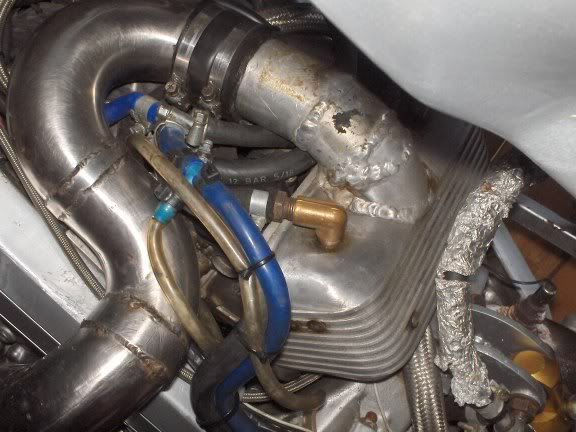
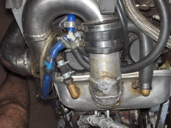
Not a lot of progress in the last week or so, as I've got bogged down in the detail on mounting the IACV, inlet air temp sensor and vacuum take offs. Still need three more vac take off on the other end!
Edited by Paul S on 9th Jun, 2007. Saul Bellow - "A great deal of intelligence can be invested in ignorance when the need for illusion is deep."
|
||||||
|
194 Posts Member #: 1296 Advanced Member Milford Haven Pembrokeshire |
10th Jun, 2007 at 10:16:06am
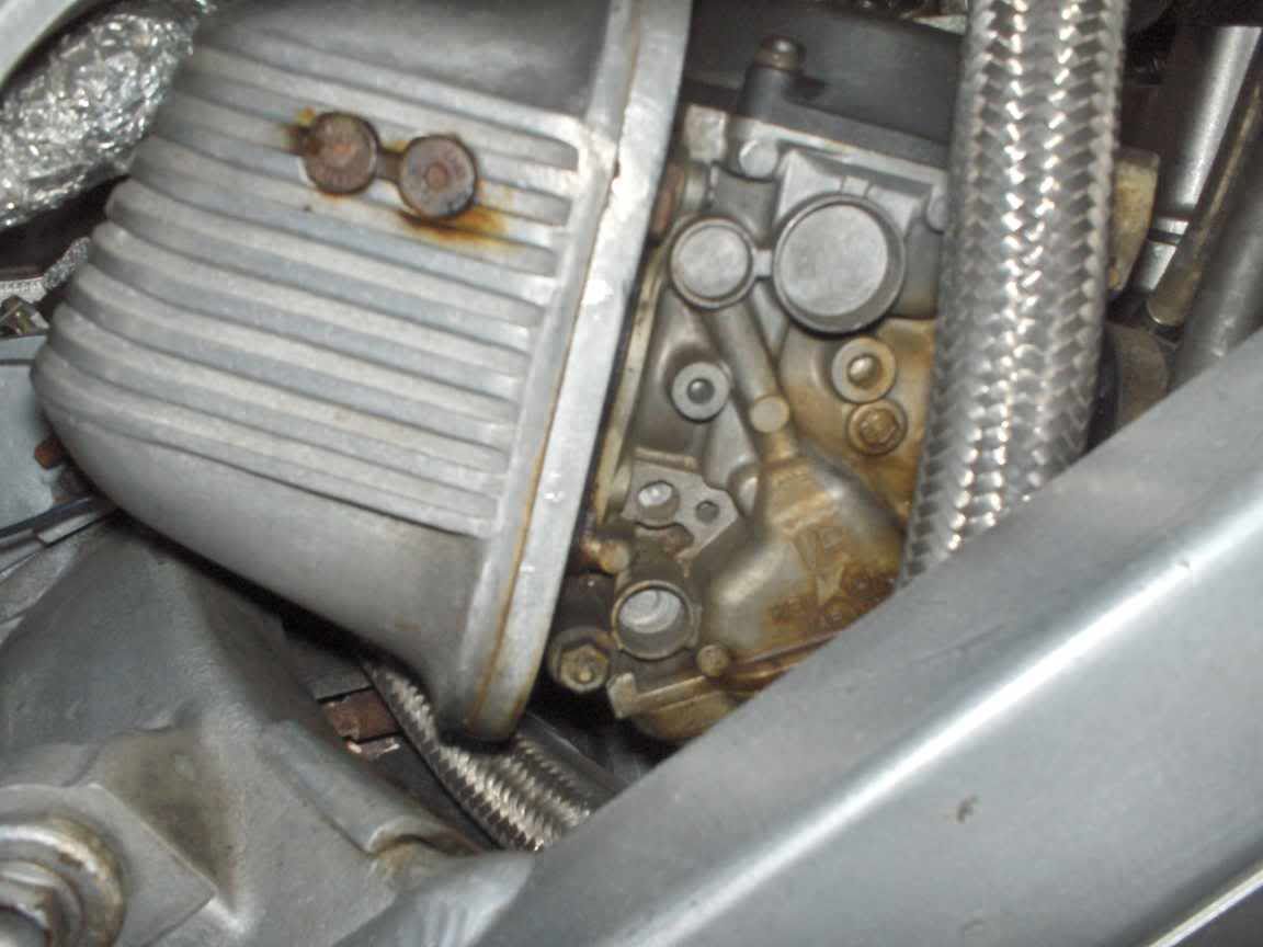
Nice work, here's how mines getting on
|
||||||
|
8604 Posts Member #: 573 Formerly Axel Podland |
10th Jun, 2007 at 10:47:32am
On 10th of Jun, 2007 at 10:16am mini23 said:
Nice work, here's how mines getting on Thats looking good. Lots of milling going on there. Are those ally parts going to bolt direct to the head or are you going to use a manifold as well? Saul Bellow - "A great deal of intelligence can be invested in ignorance when the need for illusion is deep."
|
||||||
| Home > A-Series EFI / Injection > Inlet Manifold Design | |||||||
|
|||||||
| Page: |


