Donations towards server fund so far this month.

 
£0.00 / £100.00 per month
Page:
Home > Show Us Yours! > Project "Marginal gains..."

Jimster
Site Admin

User Avatar

9404 Posts
Member #: 58
455bhp per ton
12 sec 1/4 mile road legal mini

Sunny Bridgend, South Wales

I use a golf rad in the front of my clubby, seems to cool well in race conditions with 250 - 300bhp


Attachments:

Team www.sheepspeed.com Racing

On 15th May, 2009 TurboDave said:

I think the welsh one has it right!


1st to provide running proof
of turbo twinkie in a car and first to
run a 1/4 in one!!

Is your data backed up?? directbackup.net one extra month free for all Turbo minis members, PM me for detials


alexcrosse

72 Posts
Member #: 8845
Advanced Member

My 205 had very little horse power, 150. Was a 60x180x600 core size.

The old man runs a gp4 mk2 with a JRE redtop in 291bhp @ 9000. That uses a 43x500x400.

No data like that sadly, unless a 1100nm v8 turbo diesel is any use? lol.

I really would recommend pro alloy for both advice on core sizes, and making it. They do all of our stuff and could make you a really good cooling pack. Especially with their 2l turbo experience... You do pay for it... but its not mega money considering.

Best thing to do is drop the car to them though. Give Alex or Wayne a ring and have a chat anyway.


robert

User Avatar

6748 Posts
Member #: 828
Post Whore

uranus

565mm by 280mm by 46mm are my approx. dimensions.

Edited by robert on 18th Oct, 2017.

Medusa + injection = too much torque for the dyno ..https://youtu.be/qg5o0_tJxYM


Aubrey_Boy

User Avatar

690 Posts
Member #: 9962
Post Whore

Thanks for all the replies it's all been very useful

He did say to send some photos so he could see the packaging - but to be fair the packaging in the Mini is much worse than a Cosworth - the Cossie has room in front and behind the rad so air flows through better.

I will send the photos and state the space available . I just didn't feel very confident they were going to come down 40% in core size in a worse environment based on where the discussion started. No chance of taking the car over, they'd have to make from a mock up

Cheers

Edited by Aubrey_Boy on 3rd Dec, 2014.


Paul R

User Avatar

4018 Posts
Member #: 1757
Back to Fucking Tool status

Swindon

Humm what about talking to mayoturbo (dan) he works for concept racing, they did all of nic's stuff I think.
They have some gtti rads in at the moment *smiley* not a bad size, I have been thinking of a short height rad and ducted ic over the gearbox and turbo under the drivers wing (k-series turbo and pg1 box)

Drives
-Ford S-max Mk2 Ecoboost
-Rover 100 VVC #2 - track project

Searching is all you need on TurboMinis


Aubrey_Boy

User Avatar

690 Posts
Member #: 9962
Post Whore

Cheers Paul I may look in to that, I'll just wait to see how the enquiries I have out already play out...

The top end tank is curved towards the headlamp end and feeds in from side at the top as shown by the yellow oblong.

The rad piping will be quite straight forward and tidy

I will either try and angle the rad further back at the top or see how much I can get it curved back

The oil cooler is about 20mm from the down pipe but still looks like it might work more like an oil heater than a cooler, I will probably end up with fewer rows and move it further down. It can also move about 25mm over to cold side of the turbo if I cut the upper bracket off as circled. Then I will probably have a mesh opening in the lower part of the front panel to feed air to it.

Edit:

This is the grille fitted with the rad in place but not the oil cooler, the head light is fitted to check for clearance.


The lower part of the front panel has been hacked off when I was trying to fit a long thin IC some time ago so I think once I have properly figured out what needs cutting out I will need to get another one

Cheers

Edited by Aubrey_Boy on 12th Jul, 2017.


Aubrey_Boy

User Avatar

690 Posts
Member #: 9962
Post Whore

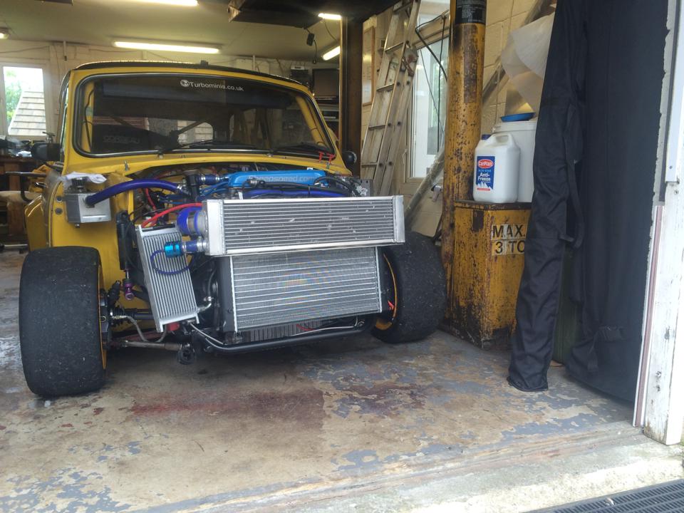
In order to try and make a decision one way or the other I got hold of a tatty secondhand Honda 1/2 size radiator so I can try it properly as I was guessing at the size of the end tanks.


The end tanks are smaller than I expected and it all fits in easier as a result, I have been able to lift the rad up so that all of the lower part of the core is exposed to direct airflow and not hidden behind the lower apron. Meaning I won't need to cut any vents into the lower front panel.


The inside of the wing rain channel also doesn't look like it will need to be cut


I have angled it back as much as I can in order to get some airflow to the top 1/3 of the rad


And if I go this route it will need a shroud to stop the air just flowing over the top of the rad


If I can make an off the shelf rad work it will save a lot of time and money as some of the quotes have been off the clock...


Cheers

Edited by Aubrey_Boy on 12th Jul, 2017.


alexcrosse

72 Posts
Member #: 8845
Advanced Member

what does your clock go up to?


Turbo This..

User Avatar

1767 Posts
Member #: 9165
Previously josh4444

Australia, brisbane

that looks neat might want to box the other sides up to the grill as well perhaps that would make some positive pressure in front wile moveing at warp speed


robert

User Avatar

6748 Posts
Member #: 828
Post Whore

uranus

get a ic in front if it too?

Medusa + injection = too much torque for the dyno ..https://youtu.be/qg5o0_tJxYM


evolotion

User Avatar

2909 Posts
Member #: 83
Post Whore

Glasgow, Scotland

as the rad is a manky one, i would defo try twisting it slightly, would make for a much neater fit if the top of the rad was twisted clockwise (looking down on it)

turbo 16v k-series 11.9@118.9 :)

Denis O'Brien.


Sir Yun

User Avatar

510 Posts
Member #: 1592
Smart Guy!

mainland europe near ze germans

just a few ideas ,
have you thought about using one of those bend bike radiators ?
also if you have a slit intake in plane with the rad with ducting to an inter cooler you don't have the problems with it being fed warm air . have a look at how an ic in a ford transit van is ducted . you only need a surprisingly modest intake surface area.

I am working on a cfd pressure distribution wind tunnel model but i have trouble cleaning the nice mini stl model i found so that it works. maybe that will be of use if i can get it to work

Edited by Sir Yun on 23rd May, 2014.

That sir, is not rust, it is the progressive mass reduction system

http://aseriesmodifications.wordpress.com/


Aubrey_Boy

User Avatar

690 Posts
Member #: 9962
Post Whore

Hi Alex,

Not sure how far my clock goes :)

But I know it probably doesn't go as far as an estimated "£800 - £950 ish" with the caveat that they thought the core surface area was marginal as well, but still talking to them.


Robert,

If only the answer to that question were 'yes' but alas no, no room at the Inn.


Hi Denis (Sorry only just noticed your signature) instead of calling you Evo,

Yeah I bought the rad for 2 reasons, 1 to make sure of the size and the second was to curve / bend it to try and angle it backwards. Two of the rad fabricators I spoke to wouldn't bend a rad but they would 'cut n shut' - so the image below was my wooden 'cut n shut'.


Making it like this really helped all of the clearances and could mean getting a larger core area so I got a S/H Ally rad to try and bend it as I am happy to give it go on this one and if it looks OK maybe get a decent Ally one and do the same to it.

Is that what you meant?

Is your rad Koyo? Do you know if all the Koyo 1/2 rads are 'N-Flo'? I only ask because I will need to relocate the inlet and outlet, if you look at the diagram below;


If I do relocate the inlet / outlet and they are 'N-Flo' I will end up having to completely re-do the end tanks to make sure I use all of the rad.

Sir Yun,

The CFD aero model sounds interesting, cleaning up the CAD surfaces can be a real pain, I haven't had to do it personally but I know that if you have to do it manually it can take ages. It's been a while and I don't know how good the auto mesh programs are now and how clean the surfaces are that they generate.

Ideally the engine bay needs to be reasonably well detailed as well to make any flow / pressure in the grille / intake area to be fully meaningful (but costs a fortune in man hours), but I have used results that just had simplified geometry 'lumps' to represent the main engine bay parts that gave reasonable correlation

Have you run anything yet? Like oil flow lines over the surface, definitely interested in any results you get. Most of the data I have seen (mostly saloon / sedan vehicles) is surprisingly similar as far as the pressure distribution goes (I am talking specifically about just the very front end / 'grille' area)

These images were picked at random from t'internet;


Because they are public domain most of them are suitably vague and only show limited pressure ranges / distribution but you can see the areas which are most likely to be high pressure (again only talking about the front face) and as the shape of the vehicles differ so does how high and how wide the main high pressure area is, a large generalisation but most if not all pressure distributions I have seen follow a similar pattern.

What software are you using?

I am aware of curved bike rads but haven't really looked into them as I assumed (rightly or wrongly) they would be too small. Serck Motorsport do ally curved motorcycle rads but I think the cores are bought in curved and are only very specific sizes are available.


I am planning to duct air to feed the IC from the yellow areas shown below (now you can see why I wasn't cleaning the surface models up *wink*) The IC would be in the passenger inner arch and there would need to be an arch inner liner etc...


The red area is taken by the turbo in so the duct will fit around it or be a part of it to give a sealed area, that's the plan at the moment anyway, but I am open to any suggestions on the IC placement / ducting.


Cheers

Edited by Aubrey_Boy on 12th Jul, 2017.


gr4h4m

User Avatar

4890 Posts
Member #: 1775
Post Whore

Chester

Jim, looks great very Carlos Fandango


On 16th May, 2014 Jimster said:
I use a golf rad in the front of my clubby, seems to cool well in race conditions with 250 - 300bhp

I run a supercharger and I don't care the TB is on the wrong side.
VEMS + 12 PSI + Liquid Intercooler = Small Bore FUN!


TurboDave16V
Forum Mod

10980 Posts
Member #: 17
***16***

SouthPark, Colorado

If you need a super-tight 90" our of your compressor housing, I reccomend you buy up a XJ6 inlet manifold. These have very right radii cast "bananas" with an ID close to that of a typical compressor outlet.

For example:
http://www.ebay.co.uk/itm/331102337936
http://www.ebay.co.uk/itm/231235390548

I've used them a few times with good results.

On 17th Nov, 2014 Tom Fenton said:
Sorry to say My Herpes are no better


Ready to feel Ancient ??? This is 26 years old as of 2022 https://youtu.be/YQQokcoOzeY


TurboDave16V
Forum Mod

10980 Posts
Member #: 17
***16***

SouthPark, Colorado


On 23rd May, 2014 gr4h4m said:
Jim, looks great very Carlos Fandango


On 16th May, 2014 Jimster said:
I use a golf rad in the front of my clubby, seems to cool well in race conditions with 250 - 300bhp


Indeed: https://www.youtube.com/watch?v=nqqZ28m8uCo

On 17th Nov, 2014 Tom Fenton said:
Sorry to say My Herpes are no better


Ready to feel Ancient ??? This is 26 years old as of 2022 https://youtu.be/YQQokcoOzeY


Sir Yun

User Avatar

510 Posts
Member #: 1592
Smart Guy!

mainland europe near ze germans

I'm using open foam and a bunch of other open source stuff. I'm just getting in to it and this seems doable if i can get the model to behave . end goal is simulating the a series intake tract .. that is quite hard it turns out :)

That sir, is not rust, it is the progressive mass reduction system

http://aseriesmodifications.wordpress.com/


evolotion

User Avatar

2909 Posts
Member #: 83
Post Whore

Glasgow, Scotland

its just a plain core with end tanks, a "single pass" design. I also read somewhere that radiator ducring is more efficient if the duct opening is smaller than the core. im buggered if I remember where tho it makes sence with the restriction imposed by the core

turbo 16v k-series 11.9@118.9 :)

Denis O'Brien.


apbellamy

User Avatar

16540 Posts
Member #: 4241
King Gaycharger, butt plug dealer, Sheldon Cooper and a BAC but generally a niceish fella if you dont mind a northerner

Rotherham, South Yorkshire

Ben has a very small opening in the front of his 'brown streak' racer for this reason.

On 11th Feb, 2015 robert said:
i tried putting soap on it , and heating it to brown , then slathered my new lube on it

*hehe!*


Joe C

User Avatar

12307 Posts
Member #: 565
Carlos Fandango

Burnham-on-Crouch, Essex

thats in Alan Staniforths race and rally care design and also IIRC Corky "Cake" Bells book.

essintially you want an opening around 1/4 the size of the core.


On 24th May, 2014 evolotion said:
its just a plain core with end tanks, a "single pass" design. I also read somewhere that radiator ducring is more efficient if the duct opening is smaller than the core. im buggered if I remember where tho it makes sence with the restriction imposed by the core

On 28th Aug, 2011 Kean said:
At the risk of being sigged...

Joe, do you have a photo of your tool?


http://www.turbominis.co.uk/forums/index.p...9064&lastpost=1

https://joe1977.imgbb.com/


Aubrey_Boy

User Avatar

690 Posts
Member #: 9962
Post Whore

Absolutely the intake area should be proportionally smaller than the core face area, this is to slow the air speed down and increase the pressure at the 'face' of the radiator

The main problem is that in order to do this you have to avoid flow separation by not making the transition too abrupt and you can only do that if there is a sensible distance between the intake opening and the rad face, for rads of this core size I'd say 200mm as minimum to try and take advantage of this.

Otherwise I think all you can do is at least try and channel the air through the rad and not let it take the easier path around it as it will do without any ducting.

The Mini has an excess of inlet area (grille) to feed any manner of water cooling rads / IC / engine intakes but just doesn't have anywhere to put the heat exchangers far enough away from it.

Edited by Aubrey_Boy on 24th May, 2014.


Sir Yun

User Avatar

510 Posts
Member #: 1592
Smart Guy!

mainland europe near ze germans

make dividers in the duct to keep the included angle down .Keeps separation in check

Edited by Sir Yun on 7th Jun, 2014.

That sir, is not rust, it is the progressive mass reduction system

http://aseriesmodifications.wordpress.com/


Aubrey_Boy

User Avatar

690 Posts
Member #: 9962
Post Whore

100% agree, as stated above when 'turbo this' suggested boxing the rad in I said I would try and use some kind of 'lead in' divider to try and direct airflow to the areas it didn't want to go to - i.e. up behind the shroud.

Unfortunately when the most of the rad is hard against the grille there is little duct to divide up but still trying alternatives as we speak - the rad size just gets so small the further into the engine bay / inner arch you go

Cheers

Edit:

I'd do it a bit like this: - again excuse my drawing skills :)


The black is sort of the outer shroud to the rad, yellow is the surface of the grille area, and the light blue a divider to try and feed the upper 1/3 without becoming hopelessly separated

Is that what you meant?

Edited by Aubrey_Boy on 12th Jul, 2017.


Sir Yun

User Avatar

510 Posts
Member #: 1592
Smart Guy!

mainland europe near ze germans

yeah that is what seems to make sense, although I think you be better off with a extra division. I think ( have to look it up) that you need less than 12 degrees included angle.

http://www.youtube.com/watch?v=nuQyKGuXJOs...EC6527BE871ABA3
skip to 22 :00

That sir, is not rust, it is the progressive mass reduction system

http://aseriesmodifications.wordpress.com/


Aubrey_Boy

User Avatar

690 Posts
Member #: 9962
Post Whore

Thanks for the link

That kind of real world flow visualisation is really interesting, I have seen dye used as a visualiser before but I don't think I have seen hydrogen bubbles before which have the added benefit of not 'polluting' the tank so you re-use it straight away.

Yeah even the relatively shallow angle diffuser they show you can see the boundary layer getting thicker and separation occurring at the outer wall, the dividers they add to remove the separation gives an almost unbelievable improvement in flow attachment. I normally use say 7 degrees as a max diffuser angle assumption so 12 degrees is only 1 degree less as an included angle so seems entirely reasonable.

As you say more dividers would be beneficial as the transition to the upper shroud in my application is massive in comparison and over a shorter distance too.

Home > Show Us Yours! > Project "Marginal gains..."
Users viewing this thread: none. (+ 1 Guests) <- Prev   Next ->
To post messages you must be logged in!
Username: Password:
Page: