Donations towards server fund so far this month.

 
£0.00 / £100.00 per month
Page:
Home > Show Us Yours! > Project "Marginal gains..."

Yo-Han

User Avatar

974 Posts
Member #: 3228
Post Whore

North of the Netherlands

Completely clueless, but WOW.. :)


On 17th Apr, 2014 Aubrey_Boy said:
Yeah the photo does a good job of hiding the pertinent bits

Attached is a screen capture video of the suspension going through its full travel and 5 degrees of roll


It's not exactly the same hard points as I am using now but is close enough and similar rising rate behaviour

Cheers

Dazed and Confused....


robert

User Avatar

6748 Posts
Member #: 828
Post Whore

uranus

that's some sexy software !

Medusa + injection = too much torque for the dyno ..https://youtu.be/qg5o0_tJxYM


Aubrey_Boy

User Avatar

690 Posts
Member #: 9962
Post Whore

Thanks for the comments,

The software is (in this context) just joints and linkages, but still an essential tool for me to get this far

In order to fit the coil overs in this inboard position I have had to change the standard starter motor for a reduction gear unit:


It's entirely unnecessary as far as needing a high torque starter motor but needed just to get the solenoid that the standard starter motor has which hits the drivers side inboard coil over.


This shows that the starter clears the coil over, the grey nylon collar around the passenger coil over is there to represent the largest outside diameter spring that I think might be needed.

The biggest issue now with the inboard coil overs is the gear linkage, my plan was not to have to modify the bulkhead to package the gear linkage but that may have to change...

Whilst this is currently my favourite photo, subsequent packaging mock ups lead me to believe that a standard round nose and an XE turbo are not compatible...


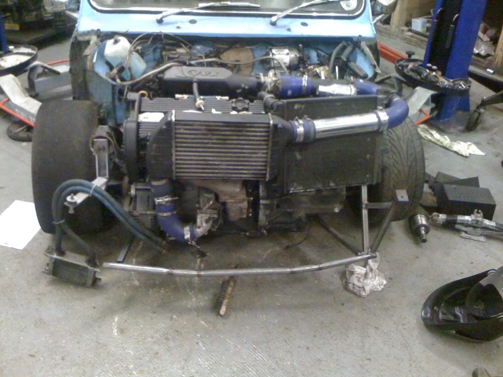
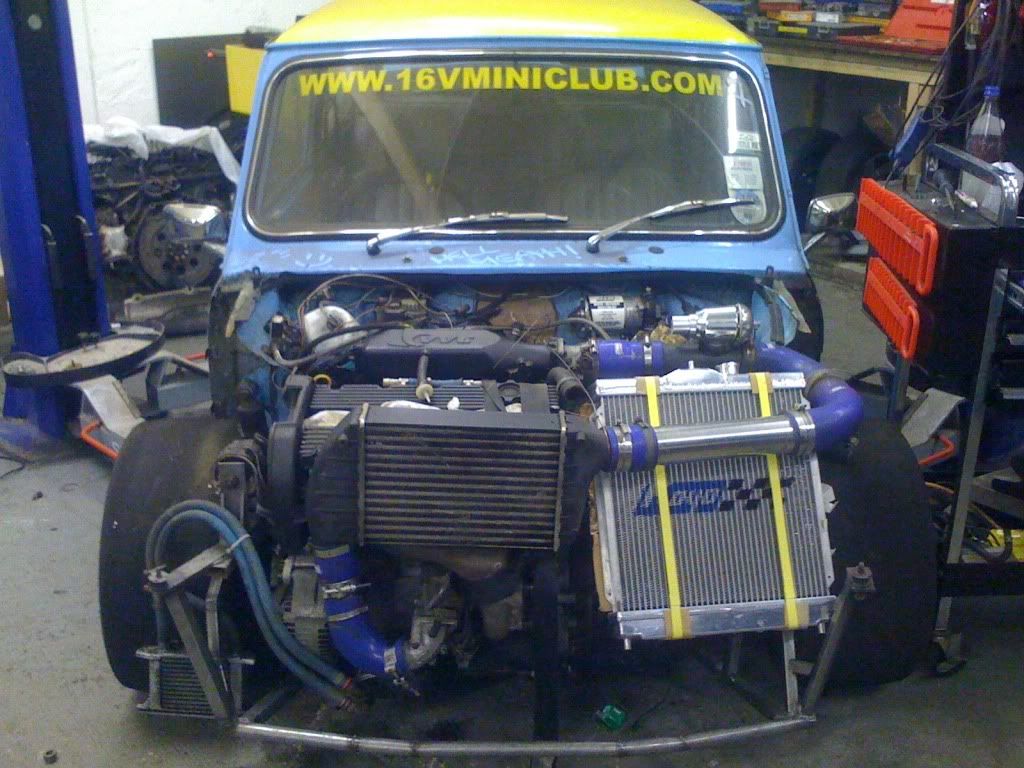
Fitting the turbo in isn't a problem and I think getting an engine cooling radiator setup is 'do-able' but getting an intercooler packaged without cutting holes in the bonnet or fitting the intercooler in front of the front panel seem to be the only options...

Let's see if the Easter bunny can hide it

Cheers


Edited by Aubrey_Boy on 12th Jul, 2017.


robert

User Avatar

6748 Posts
Member #: 828
Post Whore

uranus

you could try out the idea of a long water to air ic in the top of a wing ,then a smaller water rad in front ? I think you can fit in a 3 stage long one in the wing .someone on here did it ..russel?

Edited by robert on 23rd Apr, 2014.

Medusa + injection = too much torque for the dyno ..https://youtu.be/qg5o0_tJxYM


Aubrey_Boy

User Avatar

690 Posts
Member #: 9962
Post Whore

H Robert,

If you have any links or user name I'll have a search.

I have been looking at charge coolers as getting the bulk of a typical air to air device looks unlikely, whereas I can use a thinner core for a water to air heat exchanger and also get it made in any shape / configuration.

Cheers


Rob H

4314 Posts
Member #: 700
Formerly British Open Classic

The West Country

Robert, is this what you're thinking of?

http://www.chargecooler.co.uk/index.php?ma...680b28d31b56c79

Isambard Kingdom Brunel said:
Nothing is impossible if you are an Engineer


robert

User Avatar

6748 Posts
Member #: 828
Post Whore

uranus

it was 'turbo shed',

I have the single stage one of these in my astra

http://www.paceproducts.co.uk/public_html/...oductID=car/mr2

that's ^^^a 4 stage one .


I think russel had the 3 stage one in his wing..


maybe like this


http://www.ebay.co.uk/itm/FIESTA-Rs-Turbo-...=item258d1976a1


I think pace can do bespoke ones too.


robert

Edited by robert on 18th Oct, 2017.

Medusa + injection = too much torque for the dyno ..https://youtu.be/qg5o0_tJxYM


Aubrey_Boy

User Avatar

690 Posts
Member #: 9962
Post Whore

Cheers Robert

Unfortunately most of the 'turbo Shed' threads don't have any pics but I think I am going start off air to air and see how that goes with the IC in the inner arch area and ducting to feed it but nothing satisfactory found yet.

Been struggling with packaging of cooling rad/s and intercooler, mocked up several options but everything is so tight that I have to be 100% certain everything that needs to be in place is in place such as alternator etc.

For my reference does anyone have any info as regards what size radiators (core dimensions) that are currently being used on any of the higher horsepower / Turbo A series cars on here? And ideally a photo of the installation to see it's position / ducting.

I know my installation is likely to be completely different but I am just trying to get an idea of what has been successfully used surface area wise.

Finally made a decision on what throttle body to use, it's off a Type R Civic K20, I think it's 64mm at the butterfly


Its a Formula Renault accelerator pedal which I will try and use to start with if it fits or can be adapted in terms of size.

Cheers


Edited by Aubrey_Boy on 12th Jul, 2017.


robert

User Avatar

6748 Posts
Member #: 828
Post Whore

uranus

bit of an oblique shot, but I have a metro mk1 rad .I have never had any problems with overheating.


Edited by robert on 18th Oct, 2017.

Medusa + injection = too much torque for the dyno ..https://youtu.be/qg5o0_tJxYM


TurboDave16V
Forum Mod

10980 Posts
Member #: 17
***16***

SouthPark, Colorado

I know it's late in the day and all that, but it sure looks like putting the turbo above the gearbox might have been a better idea?

On 17th Nov, 2014 Tom Fenton said:
Sorry to say My Herpes are no better


Ready to feel Ancient ??? This is 26 years old as of 2022 https://youtu.be/YQQokcoOzeY


evolotion

User Avatar

2909 Posts
Member #: 83
Post Whore

Glasgow, Scotland

i know i run a clubby front, but i did throw a round nose front on for a laugh and wasnt too far out. im running a "half width" civic radiator infront of my gearbox, it sits to the right of the cylinder head, but then your head is larger, and the space your cramming it into is smaller, and given the neatness if your build you may not like the stupid angle i have mine at.

micra K10 radiator. this could fit under a round nose with my setup, but prolonged boosting did see the temps climb up. a better quality core may help but its marginal. probably too small for your big engine.


new setup, cooled impecably, but may require a clubby front. obv my intercooler placement is an absolute no-go for you :(

Edited by evolotion on 12th May, 2014.

turbo 16v k-series 11.9@118.9 :)

Denis O'Brien.


Paul R

User Avatar

4018 Posts
Member #: 1757
Back to Fucking Tool status

Swindon

use a fn2 civic type R accelerator pedal, will fit against the firewall for full movement :) or a peugeot 307 also (has a seperate WOT switch inbuilt for extra boost if required *wink*

Drives
-Ford S-max Mk2 Ecoboost
-Rover 100 VVC #2 - track project

Searching is all you need on TurboMinis


Aubrey_Boy

User Avatar

690 Posts
Member #: 9962
Post Whore

Thanks for taking the time to post all the pictures and info

Robert,

Thank you, every MK1 Metro rad I see seems to be different, I had one which I used for Mock up work when I was planning on NA but it had a very thin core 20mm ish with plastic end tanks with outlet and inlet on either side. Yours looks about 40mm thick, copper/metal ends and inlet and outlet on the same ends? Is it about 500mm x 260mm x 40mm?

Your setup must be secret *wink* These strange angle photos, Seriously though, good to know, what power level have you run like this?

Turbo Dave,

Don't worry I've not thrown the towel in just yet :) I tried everything to make the side mount work as I really wanted this option, In order to help fore / aft weight distribution I moved the engine back about 50mm and to help with driveshaft angles so the last thing I wanted was 10 - 12 kg hanging out the front on the side that was already heavier! Turbo over the gearbox went a long way to help the side to side weight distribution.

If I could have got the down pipe down the back of the engine it would have worked but having to bring a 2.5" DP back down the front end just took all the space away (and more) that the turbo placement saved. I tried twin smaller pipes, oval sections but couldn't make it work.

Evo,

Thanks, I have mocked up a Clubman setup not dissimilar to that, I just had the IC more in front of the rad than the engine.

Any idea of the dimensions of the rad core for either setup? as any info is useful.

The Clubman front is my fall back so there is no chance of this not working at all.

I think your rad angle is fine, I am trying to angle mine as far back as possible in the same way but I am very limited.

You say a Round nose front was very close, I reckon 10 - 20mm max longer for me then rad cooling would be sorted.

Paul,

Have you used this pedal? I looked at it but it looked a pig to package, the Formula Renault one is really narrow / small and has convenient mounts so I will give it a go.

The SQ6 ECU has lots of functions which can be mapped against any (WOT or otherwise) pedal / TB angle so a WOT switch isn't needed but could be used as a NOS system input *wink*

Cheers


Edited by Aubrey_Boy on 12th May, 2014.


robert

User Avatar

6748 Posts
Member #: 828
Post Whore

uranus

If you have a look for rr shootout in search you can read the general sort of output . I run around on 6 psi ,about 130 bhp ,then occasionally run 12 psi around 175 bhp .when racing I run up to 23 psi,and id put bhp somewhere between 230 and 260.but thats quarter mile stuff so no long term abuse at high boost.
have a look at the graphs and discussion in the shootout threads ,you might find it interesting .*wink*

the rad was deffo a mk1 metro stock one ,plastic end tanks , I know later metro rads were as you describe though .I will try to get out and measure it tomorrow.

robert

Edited by robert on 18th Oct, 2017.

Medusa + injection = too much torque for the dyno ..https://youtu.be/qg5o0_tJxYM


evolotion

User Avatar

2909 Posts
Member #: 83
Post Whore

Glasgow, Scotland

sadly I dont have access to either core at the moment, ebay is good for research if you look up a radiator from a factors they often have dimentions, the latter radiator I pictured would be intended for an ek civic though it is a good 2inches thick

turbo 16v k-series 11.9@118.9 :)

Denis O'Brien.


TurboDave16V
Forum Mod

10980 Posts
Member #: 17
***16***

SouthPark, Colorado

If the only think stopping me from putting a DP over the back of the engine was space, I'd introduce the bulkhead to my friend the plasma cutter lol

Alternativly, can you route the rigid water hose round the back of the engine round the front instead. This throws up a little more space above the starter motor doesn't it?
Final option - Why cant you still mount the turbo above the gearbox, but have the DP still going down the front of the engine, turning over the top of the gearbox bell housing and to the turbo?

On 17th Nov, 2014 Tom Fenton said:
Sorry to say My Herpes are no better


Ready to feel Ancient ??? This is 26 years old as of 2022 https://youtu.be/YQQokcoOzeY


Paul R

User Avatar

4018 Posts
Member #: 1757
Back to Fucking Tool status

Swindon

where abouts are you bassed? i have a pug deisel pedal in my garage.

http://www.ebay.co.uk/itm/PEUGEOT307-HDI-a...=item43c962f871

like this

Edited by Paul R on 13th May, 2014.

Drives
-Ford S-max Mk2 Ecoboost
-Rover 100 VVC #2 - track project

Searching is all you need on TurboMinis


Aubrey_Boy

User Avatar

690 Posts
Member #: 9962
Post Whore

Paul R,

Thanks for your offer, Is your pedal new? Due to the nature of DBW I will only use new parts for this, too much of a risk otherwise

Just curious, have you done any DBW projects? Like OEM parts with other ECU's / mix and match etc...

Dave....

:)

Trust me the DP down the back of the block / side mount (SMT) was a proper 'kin orrible carve up;

The DP was about 8mm from the inlet runners / injector placement and was close to all 4 runners (this was with a 2.5" DP having been advised to use 3" - but can't even use 2.5" at the front) - no idea of the effect on the inlet temps but didn't seem ideal

About the same distance from the body of the starter motor, they really don't like prolonged heat exposure

The water pipe was the first thing to go during the mockups and the rerouting got pretty ugly going back around the cam belt covers whilst still needing take offs for the heater / expansion tank etc.

Just below the starter motor is the jack shaft / intermediate shaft whatever you want to call it and the RH CV is directly below the block water outlet so there is no way directly down.

The steering rack combined with the starter / jack shaft / RH CV meant no room, the only way the DP could go was through the bulkhead directly into the cockpit where the back of the pedals are (would have to move the pedals at least 2.5") and then the DP couldn't go back through the toeboard until near where the floor joins the toeboard due to the steering rack - proper orrible carve up.

Redirecting the DP to the front only seemed feasible with a log manifold and single pipe to the turbo - hence no twin scroll, buy another turbo etc...

Front mount (FMT) massively simplified all of the above IMO

I am sure either could have been made to work I just thought FMT was easier / neater and would easily work with a Clubman front if all else failed.

I looked at making the headers 4>2 early on to simplify the pipework going to a SMT but was advised against it and that I should take the headers all the way to the turbo to make 4>2 at the twin scroll feeds or just go log manifold as the twin scroll advantage would be lost.

Cheers


Edited by Aubrey_Boy on 3rd Dec, 2014.


evolotion

User Avatar

2909 Posts
Member #: 83
Post Whore

Glasgow, Scotland

phoned my maw and asked her to pop out with a measuring tape, core only is 360mmx360x50 . was perfectly adequate with ~300hp on constant motorway pulls, the smaller radiator would start to creep up after a few hard pulls and id have to cruise at 80 or so for a while to let things settle again. I do also have a very small oil cooler, but it helped noticably while I was using the small radiator. if you feel your system may be marginal it may help you too, if you can find the room!

turbo 16v k-series 11.9@118.9 :)

Denis O'Brien.


Aubrey_Boy

User Avatar

690 Posts
Member #: 9962
Post Whore

Thanks very much for taking the trouble in doing that it's pretty well perfect data for me based on your HP figure *Yes*

Did you have any ducting to the rad or air feeds cut into the Clubman lower valance or was all the air routing through a conventional Clubman 'upper' grille?

Assuming round nose the IC will be inner wing mounted and fed from a front facing duct on the drivers side, if I had a running car I would be tempted to cobble up an old MAF sensor and / or a pitot in a few places to get an idea of the relative flow in a few areas, say from the grille and either in the lower valance or a duct below it.

Cheers


Edited by Aubrey_Boy on 3rd Dec, 2014.


evolotion

User Avatar

2909 Posts
Member #: 83
Post Whore

Glasgow, Scotland

no ducting atall, I had 3 extra holes where the indicator would be and when at 3 figure speeds the bonet started to curl up at the front edge, so I mounted the radiator so high it could see the air that went over the grille too. but no duct. was always on my to-do list.

turbo 16v k-series 11.9@118.9 :)

Denis O'Brien.


Custard

User Avatar

283 Posts
Member #: 8215
Senior Member

Rayleigh

Excellent build sir, way beyond me...

I've used a mk1 gold rad on my measly a series. I searched eurocar parts website for rads as they too list diamensions and pictures.

Dave the Cake


Aubrey_Boy

User Avatar

690 Posts
Member #: 9962
Post Whore

Cheers Evo,

OK, the fact you had no ducting and no additional cut outs probably gives me an additional factor of safety on top of your core / HP figures which is again good, although I don't know what additional air the bonnet lifting gives *wink* I do plan to try and fit an oil cooler as you suggest it is an additional aid to overall cooling, but again likely to be tucked away in the inner wheelarch and ducted if I am really lucky.

Cheers Dave,

Thanks, that's useful information, I think I did know that but clearly forgot it or where the drawings were so I will have mooch through the website.


alexcrosse

72 Posts
Member #: 8845
Advanced Member

Are you going for a standard rad, or just getting an idea of size and then making one / getting one made?

I'd just approach someone like ProAlloy and ask them about sizing / commission one. They did a pretty good job making my peugeot one. Hidden away from throttle body air flow, all below grill line with mounts for the fans and oil cooler.

Edited by alexcrosse on 15th May, 2014.


Aubrey_Boy

User Avatar

690 Posts
Member #: 9962
Post Whore

Hey Alex,

I was after any data as I was trying to correlate a spreadsheet I use to calculate the required radiator surface area which I have used successfully in the past, however...

I have always had access to pretty good data in terms of filling it in, such as heat rejection to the water system, heat rejection to the oil system, water mass flow rate, oil mass flow rate, water temp drop across the radiator and quite a few more.

As I don't have any of this for this setup / XE in the estimated HP condition I was having to estimate so many of the parameters which I don't have proper data for, so it became pointless, hence, it made much more sense to see what has been used and start from there.

I will most likely have the rads made as the space is such a specific size and shape and getting inlets / outlets in the correct place seems unlikely from an off the shelf rad.

I have spoke to a few rad fabricators / manufacturers but as soon as you try and get any data for the cores it's clear most of them don't have any and the suggested core sizes end up massive.

I have always used Docking Engineering cores in the past but they are pricey depending on what you use and they generally have relative data for cores, don't get me wrong I am not about to use £1000 HS Marston Motorsport cores but similarly I think that there are too many people out there making £500 - £600 'shiny' rads based around Chinese cores so I am just trying to find something in the middle.

What's the core size / HP of your 205 out of interest? :)

It's a long shot and but any of the engine stuff you are involved which could give estimates for heat rejection for a 250 - 300 Hp ish Force induction doobry in say kW or mass flow rate for the oil or water system in kg/min? PM if you prefer

Cheers

Edited by Aubrey_Boy on 16th May, 2014.

Home > Show Us Yours! > Project "Marginal gains..."
Users viewing this thread: none. (+ 1 Guests) <- Prev   Next ->
To post messages you must be logged in!
Username: Password:
Page: