| Page: |
| Home > General Chat > top arm angle on very low cars | |||||||
 690 Posts Member #: 9962 Post Whore |
23rd Dec, 2016 at 09:30:55pm
Hi James, I am happy to share the standard cone data as that is data I have measured for myself, to be honest it duplicates data which Robert has already measured, other data I have measured or had measured was at the request and cost of others so I'd need agreement to share but my guess is they'll say no as it's still relevant to any current Historic / Miglia etc running on rubber cones, standard or otherwise.
|
||||||
 690 Posts Member #: 9962 Post Whore |
23rd Dec, 2016 at 09:35:25pm
On 23rd Dec, 2016 wil_h said:
What an amazing thread this has turned in to. Great input Aubrey, learning lots. I even stick with rubber cones on the rear and accept the additional weight as I know I can make it work. Cheers Wil I can fully understand why many swear by and stick with rubber cones, it's difficult to go too far wrong, with coil overs it's easy to see how so many don't like them as it's all to easy to end up with something which is miles from where you were with cones let alone starting to improve on them. |
||||||
|
Forum Mod 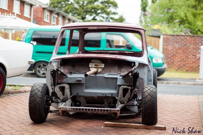 4828 Posts Member #: 154 Post Whore Midlands |
24th Dec, 2016 at 12:53:56pm
On 23rd Dec, 2016 nky_84 said:
@Nick - assume you havent driven the car with that top arm mod as yet? That looks pretty straight forward, but im guessing if you drive / model that its going to be pretty horrible / impossible to drive at the limit... I haven't yet mate, mine won't be track use though so it's not as much of a concern as most guys on here. Main reason I did it was to stop the top ball joint binding at the height I wanted to run at. On 20th Oct, 2015 Tom Fenton said:
Well here is the news, you are not welcome here, FUCK OFF. |
||||||
 489 Posts Member #: 9159 Senior Member Devon |
24th Dec, 2016 at 05:46:52pm
Thanks for sharing! The reason I asked was because I'm trying to find an alternative to the modified rubber cones on the front of my gtm coupe. Due to the front end being a lot lighter, but it seems switching to coilovers might be the way to go! |
||||||
 324 Posts Member #: 9441 Senior Member South Devon |
24th Dec, 2016 at 06:04:56pm
On 22nd Dec, 2016 wil_h said:
Top arm pivit point moving seems more sensible, but only works if using coilovers and I wanted to stay with rubber cones so never did it. Interested to hear why it wouldn't be viable with rubber cones? Obviously the Hi-Lo would need shortening to match the amount the arm is raised but assuming the pivot is moving vertically not diagonally I can't see why it wouldn't work. |
||||||
|
9258 Posts Member #: 123 Post Whore Betwix Harrogate and York |
24th Dec, 2016 at 07:46:57pm
It's just the practicalities of getting it all in. The knuckle joint doesn't line up with the centre of the cone (well not when using hydro arms), so you need a decent length of hi-lo to make the angle work.
Fastest 998 mini in the world? 13.05 1/4 mile 106mph
On 2nd Jan, 2013 fastcarl said:
the design shows a distinct lack of imagination, talk about starting off with a clean sheet of paper, then not bothering to fucking draw on it,lol On 20th Apr, 2012 Paul S said:
I'm mainly concerned about swirl in the runners caused by the tangential entry. |
||||||
 2909 Posts Member #: 83 Post Whore Glasgow, Scotland |
26th Dec, 2016 at 03:57:22pm
mines moved up an inch or so and I retained the rubber cones . hi-lo is shortened loads, and welded a caphead to the rear of the threaded section so now to adjust I use a tool(home made extra long allen key) thro the subrame hole like old hi-los that allowed me to shave away the adjusting nut too. turbo 16v k-series 11.9@118.9 :)
|
||||||
 243 Posts Member #: 1261 Senior Member Droitwich |
27th Dec, 2016 at 10:53:17am
On 26th Dec, 2016 evolotion said:
mines moved up an inch or so and I retained the rubber cones . hi-lo is shortened loads, and welded a caphead to the rear of the threaded section so now to adjust I use a tool(home made extra long allen key) thro the subrame hole like old hi-los that allowed me to shave away the adjusting nut too. This is mine, done as an experiment, if it works then I'll probly make a tube subframe. I've moved the top arm, bottom arm and damper top mount all up by 50mm. Not moved the tie bar though to level off the bottom assembly in order to try and help anti lift. Moved the lower and upper bump stops up too. The engine has gone up 30mm too to correct the driveshaft. I intend to move the damper mount inboard now because of the angle it's at as you can see. The ally cone has been replaced with an rpt part I had made at work, once I know it's all good I'll get one made in ally. Last thing to do is figure a way to do a parallel plate design on the hubs in order to move the track rod into a sensible place. |
||||||
 2909 Posts Member #: 83 Post Whore Glasgow, Scotland |
27th Dec, 2016 at 11:22:46am
yeah but IIRC Mine only went up about 30mm or so, with 50mm i dont know if youll squeese a locknut in. had a dig but dont have any pictures of what I did. suppose you could use a grub screw thro the side of the hilo to lock the thread, is a bit sketchy tho, not sure id be too happy about it. turbo 16v k-series 11.9@118.9 :)
|
||||||
 690 Posts Member #: 9962 Post Whore |
27th Dec, 2016 at 01:04:42pm
What sort of front sill line height are cars that run this low? |
||||||
 243 Posts Member #: 1261 Senior Member Droitwich |
27th Dec, 2016 at 01:34:45pm
I've set mine up so that the suspension bottoms out with the belly of the car about 1 1/2 inches off the ground. The ride height will just be set up as low as is reasonable without hitting things.. And without hitting bump stops. Something that'll be experimented with I guess when the cars going. Even with all the stuff moved up when the driveshafts are horizontal the cars not as low as it used to be when I just had it riding on bumpstops. |
||||||
 2909 Posts Member #: 83 Post Whore Glasgow, Scotland |
27th Dec, 2016 at 09:07:47pm
I cant really comment as im on metro (k series) hubs which have the top balljoint about an inch higher than the mini hubs all things equal, i did it mostly to get back to normal angles my cars not very low atall. turbo 16v k-series 11.9@118.9 :)
|
||||||
 218 Posts Member #: 9213 Senior Member Scotland |
30th Dec, 2016 at 07:36:02pm
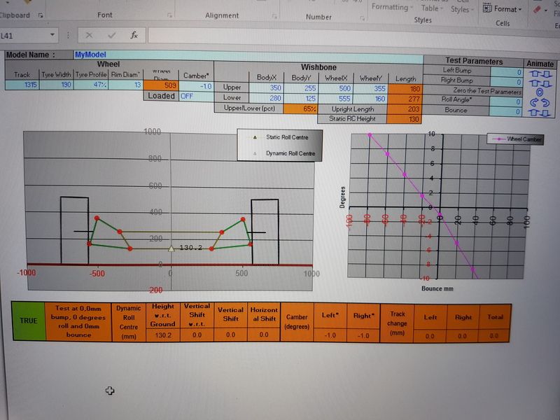
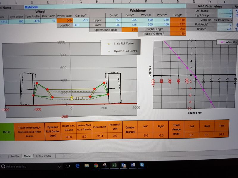
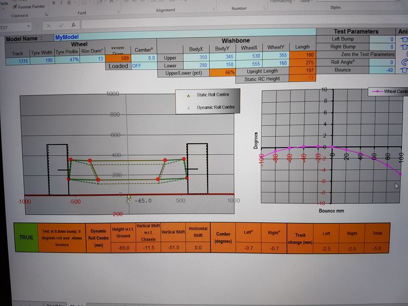
Had a go at measuring and modeling up my suspension geometry today.
|
||||||
 2975 Posts Member #: 10749 Post Whore lowestoft suffolk |
30th Dec, 2016 at 07:56:49pm
Blimey is that really what angle your arms are at when on the car? On 24th Oct, 2015 jonny f said:
Nothing gets past Dave lol NOTHING GETS PAST ME!! 
1/4 mile 14.7 @ 96mph 12psi boost Showdown class A 2nd place 18.6 @ 69mph |
||||||
|
9258 Posts Member #: 123 Post Whore Betwix Harrogate and York |
31st Dec, 2016 at 10:03:05am
Interesting that the top arm can fit at 30mm, and even 50mm movement. I think the fact that I use hydro arms made it look wrong when I looked at it.
Fastest 998 mini in the world? 13.05 1/4 mile 106mph
On 2nd Jan, 2013 fastcarl said:
the design shows a distinct lack of imagination, talk about starting off with a clean sheet of paper, then not bothering to fucking draw on it,lol On 20th Apr, 2012 Paul S said:
I'm mainly concerned about swirl in the runners caused by the tangential entry. |
||||||
 690 Posts Member #: 9962 Post Whore |
31st Dec, 2016 at 10:37:13am
Having tried to measure on car hard point positions several times I can sympathize with how difficult it is to get accurate measurements, but some of the values don't seem quite right here.
|
||||||
 218 Posts Member #: 9213 Senior Member Scotland |
31st Dec, 2016 at 11:10:05am
Yes, the ride height is maybe even a little lower than that once its on the car. you can just about make out the arms on the 2nd pic on the first page.
Edited by nky_84 on 31st Dec, 2016. |
||||||
 690 Posts Member #: 9962 Post Whore |
31st Dec, 2016 at 11:23:01am
The red line being the centreline through the taper and the ball joint and the yellow cross being the approximate centre of the ball joint itself.
Edited by Aubrey_Boy on 31st Dec, 2016. |
||||||
|
9258 Posts Member #: 123 Post Whore Betwix Harrogate and York |
31st Dec, 2016 at 12:15:09pm
Yes, I run A92, but the 4-ply fronts was the biggest change to the handling and stipping it tipping.
Fastest 998 mini in the world? 13.05 1/4 mile 106mph
On 2nd Jan, 2013 fastcarl said:
the design shows a distinct lack of imagination, talk about starting off with a clean sheet of paper, then not bothering to fucking draw on it,lol On 20th Apr, 2012 Paul S said:
I'm mainly concerned about swirl in the runners caused by the tangential entry. |
||||||
 12307 Posts Member #: 565 Carlos Fandango Burnham-on-Crouch, Essex |
31st Dec, 2016 at 07:43:21pm
just thinking out the box here.... what might work well is...
On 28th Aug, 2011 Kean said:
At the risk of being sigged... Joe, do you have a photo of your tool? http://www.turbominis.co.uk/forums/index.p...9064&lastpost=1 https://joe1977.imgbb.com/ |
||||||
 12307 Posts Member #: 565 Carlos Fandango Burnham-on-Crouch, Essex |
31st Dec, 2016 at 08:27:51pm
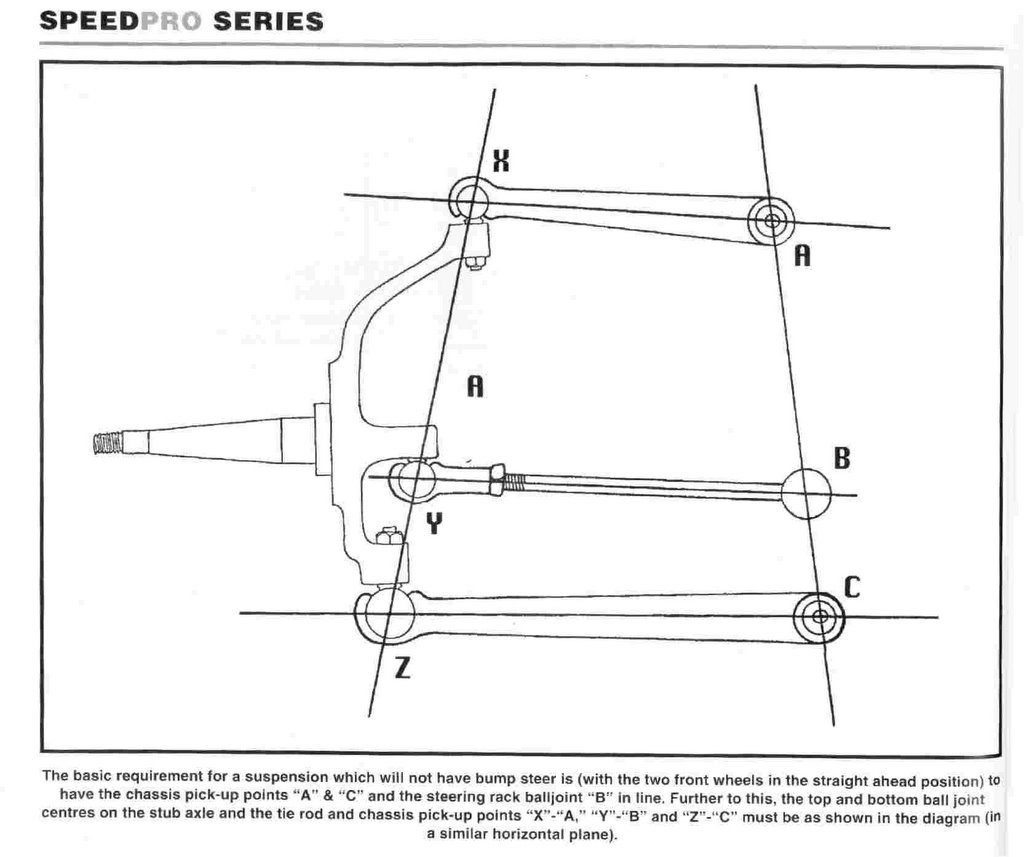
also, another thought, moving the top arm pivot straight up as a few people have done, might introduce bump steer, essentially moving that pivot changes the inner angle between the pivots, and hence puts the inner track rod end in the wrong place.
On 28th Aug, 2011 Kean said:
At the risk of being sigged... Joe, do you have a photo of your tool? http://www.turbominis.co.uk/forums/index.p...9064&lastpost=1 https://joe1977.imgbb.com/ |
||||||
 243 Posts Member #: 1261 Senior Member Droitwich |
3rd Feb, 2017 at 08:29:45pm
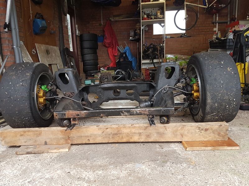
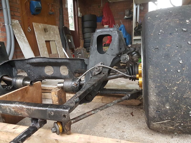
I tig brazed a lower steering arm onto my hub today to make a parallel plate type design. Purely to test how the wheel moves when it moves up and down. You couldn't do it like this in reality because when you drill out the tapered hole its on the wonk compared to the hub face (as you can see by the nut not sat properly at the top. The other reason its isnt ideal is im not sure I'd trust the braze to hold the arm in actual use. That said, it reduces the toe movement as the suspension travels significantly. You could tune it further by moving the rose joint up and down to optimise.
|
||||||
 2975 Posts Member #: 10749 Post Whore lowestoft suffolk |
3rd Feb, 2017 at 08:54:35pm
Is there anyway whatsoever to move the rack up in the toeboard? On 24th Oct, 2015 jonny f said:
Nothing gets past Dave lol NOTHING GETS PAST ME!! 
1/4 mile 14.7 @ 96mph 12psi boost Showdown class A 2nd place 18.6 @ 69mph |
||||||
|
4018 Posts Member #: 1757 Back to Fucking Tool status Swindon |
3rd Feb, 2017 at 09:47:42pm
Just a thought, rather than raising the top arm could you not raise the subframe itself into the body a bit, drop the engine in the frame to keep closer to original go but lowering the car?
Drives
|
||||||
|
4018 Posts Member #: 1757 Back to Fucking Tool status Swindon |
3rd Feb, 2017 at 09:47:43pm
Just a thought, rather than raising the top arm could you not raise the subframe itself into the body a bit, drop the engine in the frame to keep closer to original go but lowering the car?
Drives
|
||||||
| Home > General Chat > top arm angle on very low cars | |||||||
|
|||||||
| Page: |


 .
.

