| Page: |
| Home > A-Series EFI / Injection > Injection and remote turbo use | |||||||
 (2)[/url] by [url=https://www.flickr.com/photos/150672766@N03/]Rod Sugden[/url], on Fli) 5988 Posts Member #: 2024 Formally Retired Rural Suffolk |
14th Mar, 2016 at 09:59:52am
Good to here Phil, I wondered how far you had got.
Schrödinger's cat - so which one am I ??? |
||||||
|
696 Posts Member #: 10034 Post Whore Birmingham |
14th Mar, 2016 at 10:00:16am
3. (VW coil pack)
|
||||||
|
696 Posts Member #: 10034 Post Whore Birmingham |
14th Mar, 2016 at 10:27:40am
Rod, have you also seen the new LSU ADV? Bosch are marketing it as a pre turbo senor. I've yet to study the specs but my initial glance at the documents left me thinking it was not to different to the LSU 4.9. Worth taking a look...
|
||||||
 12307 Posts Member #: 565 Carlos Fandango Burnham-on-Crouch, Essex |
14th Mar, 2016 at 10:29:55am
dont really need to go cam senser for the goils as you could just fire two at once wasted spark style, although you probably need the cam sensor for the injection timing? On 28th Aug, 2011 Kean said:
At the risk of being sigged... Joe, do you have a photo of your tool? http://www.turbominis.co.uk/forums/index.p...9064&lastpost=1 https://joe1977.imgbb.com/ |
||||||
|
1267 Posts Member #: 831 Post Whore Montreal, Canada |
14th Mar, 2016 at 03:39:29pm
On 14th Mar, 2016 Joe C said:
... although you probably need the cam sensor for the injection timing? Yes |
||||||
|
1267 Posts Member #: 831 Post Whore Montreal, Canada |
14th Mar, 2016 at 03:44:43pm
On 14th Mar, 2016 PhilR said:
Rod, have you also seen the new LSU ADV? Bosch are marketing it as a pre turbo senor. I've yet to study the specs but my initial glance at the documents left me thinking it was not to different to the LSU 4.9. Worth taking a look... https://www.rbracing-rsr.com/downloads/wiri...69312011pdf.pdf I need some time to go back and compare it with the previous sensors again, but it looks in interesting at first glance. From that datasheet, it is a lot more sensitive to pressure than the 4.9 or 4.2. So it would definitely need pressure measurement and compensation. |
||||||
 834 Posts Member #: 2017 Post Whore Warwick. |
18th Apr, 2016 at 09:23:51pm
Hello,
David. |
||||||
|
8604 Posts Member #: 573 Formerly Axel Podland |
19th Apr, 2016 at 08:28:07am
On 18th Apr, 2016 mini93 said:
I have bought myself X3 LC-2 wideband kits, but with wanting to have a gauge display ont he dash. Does anyone know if I get rid of the 3rd LC-2 and replace it with the Innovate MTX-L. This'll be the post turbo, true AFR reading which I want to keep an eye on over-alls. http://www.innovatemotorsports.com/products/MTXL.php It appears to operate in a similar way with the out-puts which will feed to the ECU. No problem with mixing the LC-2 and the MTX-L. They both have the 0-5v output or could be daisy-chained and connected by serial using a third party device. On 18th Apr, 2016 mini93 said:
So my last bunch of questions I was contemplating ITB style, a throttle per-port. Going against that, I've got 2nd hand a 55mm AT power throttle body. Looking at getting an inlet manifold made up soon, still thinking about the injector arrangement, this is the part of the injection side im rather fuzzy on, so bare with me: Paul mentioned in answer to my earlier question about the issues of single injector per cylinder use, and to use a smaller injector at low RPM's. Do I keep the injector open over the 2 valve cycles? or can I open and close an injector within the short window twice, but timed to inject an the exact time for valve opening? seen on another thread talking about the fuel gathering around the closed valve which'll draw in upon opening. Same question about the larger injector which'll phase in at higher RPM, and will this injector cut off the first injector or just add in to boost the required fuel to the correct level? You can pretty much do it any way you choose. The only potential issue is that if you don't stage the injectors, at idle, the pulse widths will be too low if you are fueling for around 200hp. I'm starting with a single pulse that feeds both cylinders during the inlet valve event. That will give me a reference point for the injection timing. I then plan on bringing in all four primary injector outputs paired up to a single injector on each port and reducing the injection timing by around 90 degrees. Same for the secondary injectors. So 2 injectors per port, primary and secondary, all injectors squirting through the open inlet valve. I stage the secondaries in in boost rather than rpm. It's the increase in power that needs more fuel, not necessarily rpm. The secondaries add extra fuel rather than take over from the primaries. That's is how I did the 1293, but got limited run time before a change of plan. On 18th Apr, 2016 mini93 said:
So... Kinda what I had as an idea for inlet manifold arrangement... Dont take the piss too much out of my crude drawing... 
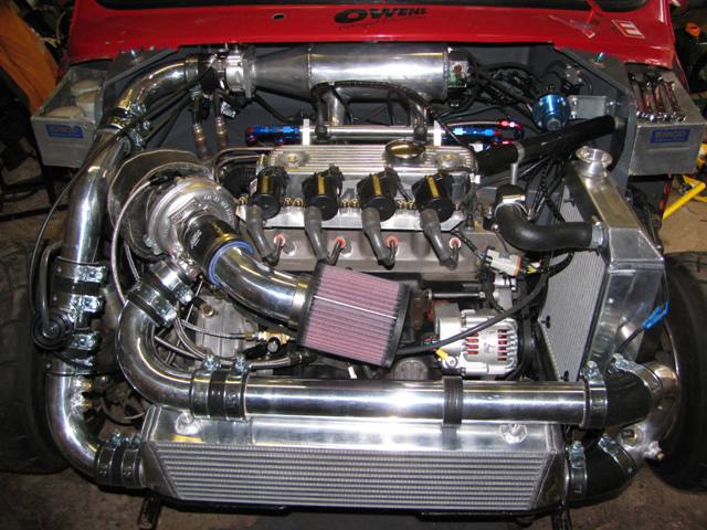
So, I can line the primary injectors up in the runners and have a fuel rail connecting the two together, then loop back and feed the top two connected secondary injectors (then to regulator bla bla) Does that seem like a reasonable idea? Throttle body I was planning on having direct bolting to the face of the plenum and sensors, map feed, what ever, on the other end feed into the opposing side. I dont image I have to worry too much about designed in shape here as I'm only feeding two runners. That's similar to my 998: 
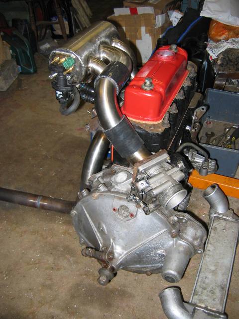
That worked well. I always had a nagging suspicion that the underslung injectors were not optimal, so I've now got the injectors on top, side by side. I did some CFD on a TB just bolted to the end of the plenum and the results were not great. On the 1293 we added a taper, but we were not hindered by master cylinders in that case. If you designing a manifold bear in mind that runner length has a massive impact on your torque curve. At least 300mm from bellmouth to head flange if you can get it in. I've even fitted a weber box on one of the cars so that we can get the plenum well away from the engine. Then centre fed the plenum similar to the 998 above. Edited by Paul S on 19th Apr, 2016. Saul Bellow - "A great deal of intelligence can be invested in ignorance when the need for illusion is deep."
|
||||||
 (2)[/url] by [url=https://www.flickr.com/photos/150672766@N03/]Rod Sugden[/url], on Fli) 5988 Posts Member #: 2024 Formally Retired Rural Suffolk |
19th Apr, 2016 at 09:38:44pm
Re. the widebands you could just buy a seperate gauge to go with the third LC-2.
Schrödinger's cat - so which one am I ??? |
||||||
 834 Posts Member #: 2017 Post Whore Warwick. |
24th Apr, 2016 at 08:08:36pm
Thanks for the replies guys.
On 19th Apr, 2016 Paul S said:
You can pretty much do it any way you choose. The only potential issue is that if you don't stage the injectors, at idle, the pulse widths will be too low if you are fueling for around 200hp. I'm starting with a single pulse that feeds both cylinders during the inlet valve event. That will give me a reference point for the injection timing. I then plan on bringing in all four primary injector outputs paired up to a single injector on each port and reducing the injection timing by around 90 degrees. Same for the secondary injectors. So 2 injectors per port, primary and secondary, all injectors squirting through the open inlet valve. I stage the secondaries in in boost rather than rpm. It's the increase in power that needs more fuel, not necessarily rpm. The secondaries add extra fuel rather than take over from the primaries. That's is how I did the 1293, but got limited run time before a change of plan. I understand the first part from my previous readings. I had already intended on running smaller injectors due to the short pulse widths (injector size unknown... will research this later!) 2nd part got me a little confused, so do you take the primary injector and keep it open with a single, longer pulse, so that its open over both inlet events? Also unsure when you refer to the 4 primary outputs paired to a single injector? 3rd part, makes sense, the secondary injectors adding more fuel on demand (I'd hazzard a guess saying if the system was to phase out the primary injectors it wouldn't lead to a smooth delivery also?) On 19th Apr, 2016 Paul S said:
That worked well. I always had a nagging suspicion that the underslung injectors were not optimal, so I've now got the injectors on top, side by side. I did some CFD on a TB just bolted to the end of the plenum and the results were not great. On the 1293 we added a taper, but we were not hindered by master cylinders in that case. If you designing a manifold bear in mind that runner length has a massive impact on your torque curve. At least 300mm from bellmouth to head flange if you can get it in. I've even fitted a weber box on one of the cars so that we can get the plenum well away from the engine. Then centre fed the plenum similar to the 998 above. Curious as to why you had the suspicions it wasn't optimal with the underslung injectors? My reasoning was that you could get a much straighter aim into the air-flow? If heat was a concern, I have a side mounted turbo set-up which i'll be getting Zercotec coated to reduce temperatures hopefully. 
I have seen previously CFD's for plenum's over multiple runners, I had assumed as I was only feeding across 2 runners it wouldn't be a problem? I guess that's why you have a centre fed plenum for the 998, to alieviate any biasing? As you see from the image above, I don't really have concerns about space, nor master cylinders with the rather deep bulkhead box. I was looking at it from a packaging point of view. I may have to look at a tapered plenum in this case. Thanks again for your input, much appreciated. David. |
||||||
 (2)[/url] by [url=https://www.flickr.com/photos/150672766@N03/]Rod Sugden[/url], on Fli) 5988 Posts Member #: 2024 Formally Retired Rural Suffolk |
24th Apr, 2016 at 10:26:21pm
On 24th Apr, 2016 mini93 said:
But I have to admit, I'm not too clued up with the daisy chaining stuff? What does it entail? I guess then I dont need to occupy 3 of the inputs between the M.S? I only did a brief google a short while back and didnt turn up much results, if anyone can shed light or link me/tell me where to go research It would be great. I'll just answer about that one for the moment. Most of the Innovate stuff has a serial port as well as the two analogue outputs. To most people it's just to hook one of the devices to a laptop to display stuff on a laptop, change the analogue outputs between narrow and wideband, set up custom calibrations etc. but, in addition, the serial ports output the accurate digital data (which is what you see on a laptop) and can be all connected in a string for certain external hardware to read the digital data of up to eight compatible items together. The difference between the digital data and the normal analogue is that it is much more accurate because ground offsets, voltage variations and noise effects are all eliminated. (I'll avoid a long complex explanation as to why but digital is better but 95% of people find analogue fine so the real "benefit" of digital for most people is the "by-product" of being able to daisy chain the controllers). You will have to read the Innovate instructions for your individual items as to how to connect them together. It generally involves buying more cables and can be a right mess as they changed the connectors from simple 2,5mm jacks on the early stuff to a mini-molex type connector on later stuff and hence make all sorts of (expensive) adaptor cables. (BTW, although I use a fully digital setup, I do not use Innovate, partly because of my comments above but mainly because I find the 14point7 digital setup much simpler and more reliable). Next, there are very few ECUs/EMS brands that accept the Innovate digital data from this daisy chain. That includes the MS range, so you need something inbetween to handle the digital data and pass it to the CPU of your chosen ECU/EMS. I'm sure Innovate sell something that would work, but with an MS2 (me) or MS3 the usual item is one of Jean's IOx range. I takes the Innovate digital data (or 14point7 in my case) and transfers it over the MS2/3 CAN databus to the MS2 or MS3 CPU. CAN is an automotive standard databus, every modern car has it, and the MS2/3 were designed with it included although most people don't use it. It can do a lot more than just AFR data, if you are considering this, read up on the MS-Extra pages and forums. At this point it should be obvious this isn't straightforward, there can be a lot of DIY involved. Maybe less so if you buy all the Innovate cables, but the IOx interface still needs housing (should be enough room in the MS3 case for the "Tiny-IOx variant) and power and CAN connecting up, then it all needs to be configured in TunerStudio, etc, etc, etc. What you then do with it will vary - I'm not familiar with an MS3 setup as to how you set multiple AFR inputs up for closed loop EGO etc, especially as the MS3 doesn't do 5 port the way I'm used to with an MS2 - but, as a bare minimum it allows you to display and datalog all the AFRs simultaneously without using a single analogue input on the MS2/3. If that hasn't put you off I can add some more but I've written too much already for a "simple" explanation. Schrödinger's cat - so which one am I ??? |
||||||
|
8604 Posts Member #: 573 Formerly Axel Podland |
25th Apr, 2016 at 08:57:52am
On 24th Apr, 2016 mini93 said:
I saw the Innovate stuff can be connected to another gauge, but to be honest... I'm a bit of a tart, and I prefer the MTX-L gauge face than the DB style which "bolts on" to the LC-2. I'll just have to flog or moth-ball the spare till I need it. But I have to admit, I'm not too clued up with the daisy chaining stuff? What does it entail? I guess then I dont need to occupy 3 of the inputs between the M.S? I only did a brief google a short while back and didnt turn up much results, if anyone can shed light or link me/tell me where to go research It would be great. As usual, there's more than one way of dealing with the multiple O2 sensor issue. I'm going to use the 0-5v signal, but also initially use the serial daisychain to establish the errors, if there are any worth worrying about. The 0-5v signal can then be calibrated to give an accurate reading. The story so far: http://www.turbominis.co.uk/forums/index.p...d=559956&fr=175 On 24th Apr, 2016 mini93 said:
2nd part got me a little confused, so do you take the primary injector and keep it open with a single, longer pulse, so that its open over both inlet events? Also unsure when you refer to the 4 primary outputs paired to a single injector? Yes single long pulse, open injector during both inlet events. Using 2 primaries and 2 secondaries initially to get a good tune before experimenting with using paired up 4 primaries and 4 secondaries on 4 injectors and splitting the pulse to per cylinder. On 24th Apr, 2016 mini93 said:
Curious as to why you had the suspicions it wasn't optimal with the underslung injectors? My reasoning was that you could get a much straighter aim into the air-flow? If heat was a concern, I have a side mounted turbo set-up which i'll be getting Zercotec coated to reduce temperatures hopefully. More of a gut feeling about the underslung injectors. I think that there is potential for puddling in the manifold with the lower injectors, particularly when cold. On 24th Apr, 2016 mini93 said:
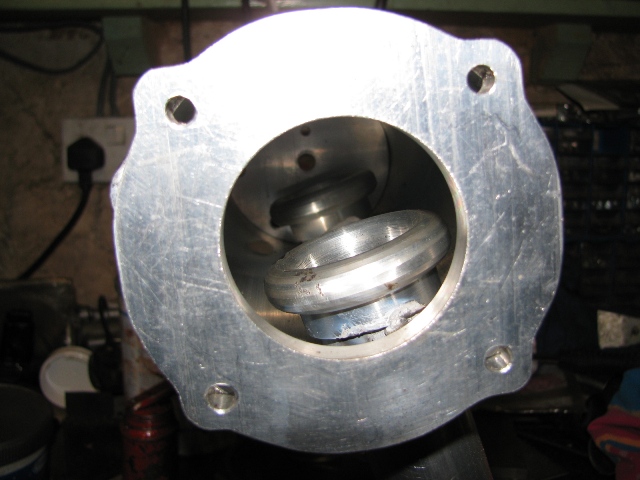
I have seen previously CFD's for plenum's over multiple runners, I had assumed as I was only feeding across 2 runners it wouldn't be a problem? I guess that's why you have a centre fed plenum for the 998, to alieviate any biasing? As you see from the image above, I don't really have concerns about space, nor master cylinders with the rather deep bulkhead box. I was looking at it from a packaging point of view. I may have to look at a tapered plenum in this case. Going back through my records, I didn't actually identify any issues with the CFD. It was only after tacking the manifold together that I saw this: 
So I then put a taper between the plenum and the TB. 
Edited by Paul S on 25th Apr, 2016. Saul Bellow - "A great deal of intelligence can be invested in ignorance when the need for illusion is deep."
|
||||||
| Home > A-Series EFI / Injection > Injection and remote turbo use | |||||||
|
|||||||
| Page: |

