| Page: |
| Home > A-Series EFI / Injection > DC Motor Control from ECU ??? | |||||||
 (2)[/url] by [url=https://www.flickr.com/photos/150672766@N03/]Rod Sugden[/url], on Fli) 5988 Posts Member #: 2024 Formally Retired Rural Suffolk |
10th Nov, 2013 at 07:39:27pm
Colin,
Schrödinger's cat - so which one am I ??? |
||||||
|
3588 Posts Member #: 655 Post Whore Northern Ireland |
10th Nov, 2013 at 08:16:55pm
On 10th Nov, 2013 Sprocket said:
working back from a 125amp draw on my starter motor at 11.5v would confirm the 1.4KW but remember that when the alternator is producing, the voltage is ~14.5v so urrent will be more like 95amps at full load. also taking into consideration the pump power absorption without the fan has been estimated at 1.5hp which is more like 75amps at 14.5v But then you already know this :) 125A to turn the engine over.... It would be one hell of a water pump to need 125A to drive it ! 9.85 @ 145mph
|
||||||
 11046 Posts Member #: 965 Post Whore Preston On The Brook |
10th Nov, 2013 at 10:33:13pm
On 10th Nov, 2013 Rod S said:
Colin, Please try to stick with metric, it's what we work in as engineers, I have to get my calculator out when you quote "1.5hp"..... Your figures are correct but I guess the point Paul is trying to show is that it doesn't need 1.12KW to circulate an adequate amount of water through the engine with a reasonably designed impellor. Rod. Rod, as an Engineer you should be able to work with any type of unit  Its just convenient to use one or the other which sometimes just is not the case. Complain about it or get on with it, it's still the same thing. Its just convenient to use one or the other which sometimes just is not the case. Complain about it or get on with it, it's still the same thing.
Since the subject originaly started with the suggestion that the mechanical pump and fan saps power from the engine, that KAD have measured this on their dyno, and that figure is quoted in horsepower, is why I state the power absorption figure in horsepower, and the only reason. As a general rule 0.75kw is roughly 1 horsepower (for ease of conversion) On 26th Oct, 2004 TurboDave16v said:
Is it A-Series only? I think it should be... So when some joey comes on here about how his 16v turbo vauxhall is great compared to ours, he can be given the 'bird'... On 26th Oct, 2004 Tom Fenton said:
Yep I agree with TD........ |
||||||
 11046 Posts Member #: 965 Post Whore Preston On The Brook |
10th Nov, 2013 at 10:35:52pm
On 10th Nov, 2013 stevieturbo said:
On 10th Nov, 2013 Sprocket said:
working back from a 125amp draw on my starter motor at 11.5v would confirm the 1.4KW but remember that when the alternator is producing, the voltage is ~14.5v so urrent will be more like 95amps at full load. also taking into consideration the pump power absorption without the fan has been estimated at 1.5hp which is more like 75amps at 14.5v But then you already know this :) 125A to turn the engine over.... It would be one hell of a water pump to need 125A to drive it ! You obviously have not understood my post On 26th Oct, 2004 TurboDave16v said:
Is it A-Series only? I think it should be... So when some joey comes on here about how his 16v turbo vauxhall is great compared to ours, he can be given the 'bird'... On 26th Oct, 2004 Tom Fenton said:
Yep I agree with TD........ |
||||||
|
126 Posts Member #: 10212 Advanced Member Sleaford Lincolnshire |
11th Nov, 2013 at 06:54:24am
Hi Sprocket
|
||||||
|
126 Posts Member #: 10212 Advanced Member Sleaford Lincolnshire |
11th Nov, 2013 at 07:13:07am
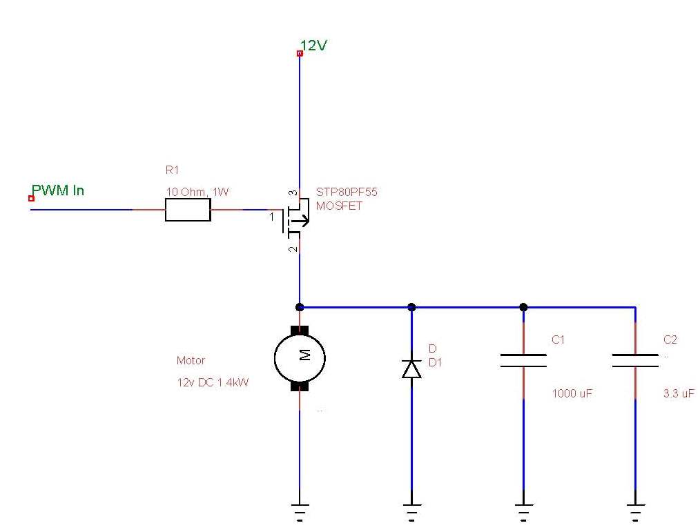
Something LIKE this
Edited by Jawd on 11th Nov, 2013. |
||||||
|
8604 Posts Member #: 573 Formerly Axel Podland |
11th Nov, 2013 at 09:40:35am
We have one of those cars, the amps they draw is beyond belief. However, the circuits are overkill and do not interface with what I'm trying to do.
Edited by Paul S on 11th Nov, 2013. Saul Bellow - "A great deal of intelligence can be invested in ignorance when the need for illusion is deep."
|
||||||
 12307 Posts Member #: 565 Carlos Fandango Burnham-on-Crouch, Essex |
11th Nov, 2013 at 11:27:50am
is using a starter motor a good idea?
On 28th Aug, 2011 Kean said:
At the risk of being sigged... Joe, do you have a photo of your tool? http://www.turbominis.co.uk/forums/index.p...9064&lastpost=1 https://joe1977.imgbb.com/ |
||||||
|
8604 Posts Member #: 573 Formerly Axel Podland |
11th Nov, 2013 at 11:48:33am
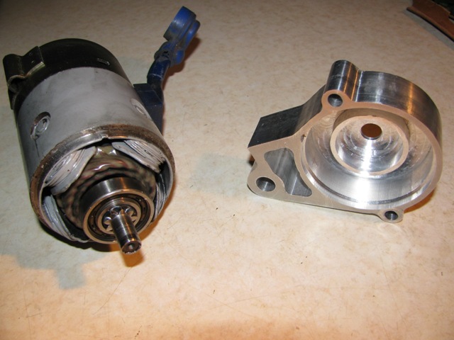
Let's be clear that this motor is nothing like a conventional mini starter motor. The Toyota starters are internally geared at about 4:1. They must run up to about 8000rpm to crank the engine over at 200rpm.
Saul Bellow - "A great deal of intelligence can be invested in ignorance when the need for illusion is deep."
|
||||||
 (2)[/url] by [url=https://www.flickr.com/photos/150672766@N03/]Rod Sugden[/url], on Fli) 5988 Posts Member #: 2024 Formally Retired Rural Suffolk |
11th Nov, 2013 at 03:07:04pm
On 10th Nov, 2013 Sprocket said:
Rod, as an Engineer you should be able to work with any type of unit  Its just convenient to use one or the other which sometimes just is not the case. Complain about it or get on with it, it's still the same thing. Its just convenient to use one or the other which sometimes just is not the case. Complain about it or get on with it, it's still the same thing.Colin, you are absolutely right.... I'm so old I can use both, but I really prefer metric (SI) - it's so much simpler. And I like complaining 
Paul, as I mentioned earlier, starter motors are not designed to be efficient so I have some sympathy with Joe's comments. They are designed for maximum torque for a short period of time. The high speed (motor) geared ones will obviously be better than the older designs but they will still be compromised on magnetic core size just to keep the weight down and hence why they are not 100% rated. But if all your other calculations come good, it shouldn't run too far into the in-efficiency region. Let's see some results.... EDIT - and Colin, I'm not suggesting the KAD figures are wrong (whichever units we prefer to use) but more to the point that the power absorbtion figures simply aren't required so are a waste. Drive a pump through a belt so it matches engine speed, and design the impellor/housing so it works well at low speed, is just throwing away power (and creating additional heat) at high speed. Edited by Rod S on 11th Nov, 2013. Schrödinger's cat - so which one am I ??? |
||||||
 2909 Posts Member #: 83 Post Whore Glasgow, Scotland |
11th Nov, 2013 at 09:55:56pm
On 10th Nov, 2013 Rod S said:
Paul can't do that (easily) as the negative side of the motor windings are connected to the case. feeling a bit special now i never even considered that. Reason i brought it up is most (all?) solid state controlled devices with heavy current draw in the automotive world seem to be switched on the ground side, so suitable drivers seem to be a bit more plentifull. turbo 16v k-series 11.9@118.9 :)
|
||||||
|
8604 Posts Member #: 573 Formerly Axel Podland |
12th Nov, 2013 at 09:05:30am
OK, so before I start cutting metal to make the motor mount, can anyone recommend a suitable motor, at least 500W and 5000rpm.
Edited by Paul S on 12th Nov, 2013. Saul Bellow - "A great deal of intelligence can be invested in ignorance when the need for illusion is deep."
|
||||||
 (2)[/url] by [url=https://www.flickr.com/photos/150672766@N03/]Rod Sugden[/url], on Fli) 5988 Posts Member #: 2024 Formally Retired Rural Suffolk |
12th Nov, 2013 at 10:06:21am
On 12th Nov, 2013 Paul S said:
OK, so before I start cutting metal to make the motor mount, can anyone recommend a suitable motor, at least 500W and 5000rpm. Or would I have more success looking for hen's teeth???? As rare as hen's teeth, probably at the price of a stater motor but they do exist. One bit of engineering I used to be into when I was a lot younger was 5" gauge railways. Specialist 12V traction motors were (back then at least) available in 250, 500 and 750W versions. But not cheap... Another one favoured by model engineers was the Sinclair C5 motor but I think it was only 250W A final possibility is things like motability scooters / wheelchairs etc. (although a lot of them will be 24V) but should readily be available secondhand. But, as I said before, although a starter motor will have a small magnetic core (and as Joe says, probably a poor turn per volt ratio), if you're not going to load it up to the very high torque it was designed to produce (for short periods of time) then you may not reach magnetic saturation or lack of back EMF in the windings. And the geared ones, with the motors running at much higher speeds, will be more efficient anyway ie, if you are only using 1/3 - 1/2 of it's potential output, it may well be fine. Try it, and monitor its temperature, a very simple way of measuring electrical and magnetic in-efficiency. Schrödinger's cat - so which one am I ??? |
||||||
|
8604 Posts Member #: 573 Formerly Axel Podland |
12th Nov, 2013 at 10:46:35am
Thanks Rod.
Saul Bellow - "A great deal of intelligence can be invested in ignorance when the need for illusion is deep."
|
||||||
|
8604 Posts Member #: 573 Formerly Axel Podland |
12th Nov, 2013 at 01:23:52pm
No going back now Saul Bellow - "A great deal of intelligence can be invested in ignorance when the need for illusion is deep."
|
||||||
 (2)[/url] by [url=https://www.flickr.com/photos/150672766@N03/]Rod Sugden[/url], on Fli) 5988 Posts Member #: 2024 Formally Retired Rural Suffolk |
12th Nov, 2013 at 05:02:03pm
Good start...
Schrödinger's cat - so which one am I ??? |
||||||
|
126 Posts Member #: 10212 Advanced Member Sleaford Lincolnshire |
12th Nov, 2013 at 05:11:15pm
Paul
|
||||||
|
8604 Posts Member #: 573 Formerly Axel Podland |
12th Nov, 2013 at 05:21:00pm
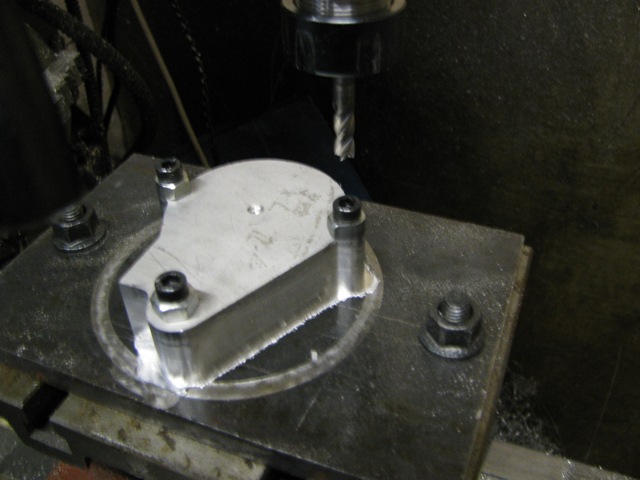
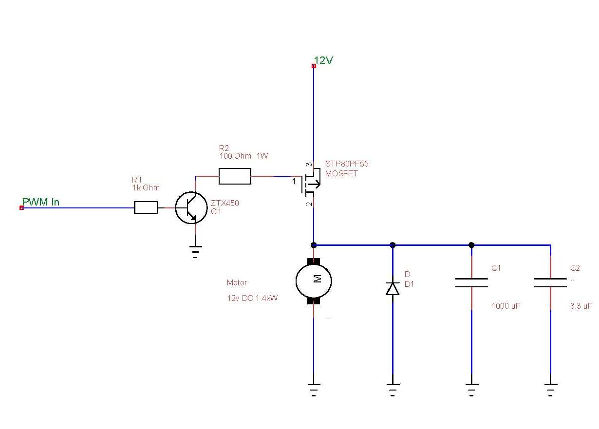
Slight change of plan.
Saul Bellow - "A great deal of intelligence can be invested in ignorance when the need for illusion is deep."
|
||||||
|
1267 Posts Member #: 831 Post Whore Montreal, Canada |
12th Nov, 2013 at 09:54:10pm
Paul,
|
||||||
|
8604 Posts Member #: 573 Formerly Axel Podland |
14th Nov, 2013 at 03:35:17pm
Bracket/End Cover now finished:
Saul Bellow - "A great deal of intelligence can be invested in ignorance when the need for illusion is deep."
|
||||||
 12307 Posts Member #: 565 Carlos Fandango Burnham-on-Crouch, Essex |
14th Nov, 2013 at 04:12:23pm
THAT is a nice bit of bracketry! On 28th Aug, 2011 Kean said:
At the risk of being sigged... Joe, do you have a photo of your tool? http://www.turbominis.co.uk/forums/index.p...9064&lastpost=1 https://joe1977.imgbb.com/ |
||||||
|
8604 Posts Member #: 573 Formerly Axel Podland |
15th Nov, 2013 at 02:35:59pm
On 10th Nov, 2013 Rod S said:
Mounting - ideally on a purpose made PCB (we can think about that later) but the main thing is to support the legs relative to the bolt/heatsink hole so, for a test, what I would suggest is a bit of veroboard with a nice slab of 1/8" (3mm) aluminium down one side - visualise the standard MS3 board and its simple heatsink but make it larger. And remove the copper from the veroboard where the bolts go through. How the fook do you drill veroboard without it snapping.......Grrrrrrrrrrr Saul Bellow - "A great deal of intelligence can be invested in ignorance when the need for illusion is deep."
|
||||||
 (2)[/url] by [url=https://www.flickr.com/photos/150672766@N03/]Rod Sugden[/url], on Fli) 5988 Posts Member #: 2024 Formally Retired Rural Suffolk |
15th Nov, 2013 at 06:37:08pm
On 15th Nov, 2013 Paul S said:
How the fook do you drill veroboard without it snapping.......Grrrrrrrrrrr Really carefully I guess 
I hate the stuff, I only ever use it for prototyping, once I know a circuit works, either veroboard or breadboard, I KiCad it and get a proper PCB made in HK/China for very little cost. Seriously though, you need a really sharp drill if you want to enlarge holes in VeroBoard, and go through slow at a high drill speed. Schrödinger's cat - so which one am I ??? |
||||||
|
8604 Posts Member #: 573 Formerly Axel Podland |
16th Nov, 2013 at 09:10:59am
Sorted now. I was milling off the copper then drilling.... not good.
Saul Bellow - "A great deal of intelligence can be invested in ignorance when the need for illusion is deep."
|
||||||
|
8604 Posts Member #: 573 Formerly Axel Podland |
16th Nov, 2013 at 03:54:01pm
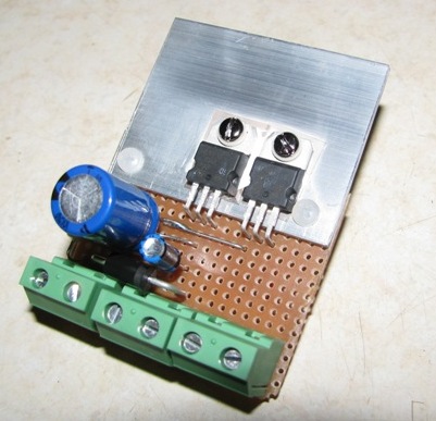
Circuit built:
Saul Bellow - "A great deal of intelligence can be invested in ignorance when the need for illusion is deep."
|
||||||
| Home > A-Series EFI / Injection > DC Motor Control from ECU ??? | |||||||
|
|||||||
| Page: |

