| Page: |
| Home > A-Series EFI / Injection > MS extra siamese sequential tune (msq) to start with | |||||||
 (2)[/url] by [url=https://www.flickr.com/photos/150672766@N03/]Rod Sugden[/url], on Fli) 5988 Posts Member #: 2024 Formally Retired Rural Suffolk |
7th Dec, 2009 at 04:20:35pm
On 7th Dec, 2009 Paul S said:
I hope you guys are going to persevere with the dual pulse mode. I'm certainly going to run with it initially (once I'm actually on the road....) as, in theory, if the injector capacity is large enough (so keeping pulse width low), it must work. Once the first of us is onto staged injection with multiple (or large) injectors, it will become more interesting I think. Onwards and upwards..... Schrödinger's cat - so which one am I ??? |
||||||
|
1267 Posts Member #: 831 Post Whore Montreal, Canada |
7th Dec, 2009 at 04:25:30pm
On 7th Dec, 2009 Paul S said:
I hope you guys are going to persevere with the dual pulse mode. I could not get it to work at above 3000rpm, but that was with an early version of the code that may not have been handling the pulses merging as expected. Another problem is that although in theory you have a VE table and an Injection Timing table for Inner and Outer cylinders respectively, they do not operate independantly. If you change settings to improve the AFR on the inner cylinders, then the AFR on the outers also change. I agree that it would be good to try it again with another setup. But since the 2 cylinders do share the same port, all the fueling coming from wall wetting (which will never be nil unless doing direct injection) will affect both cylinders and this wall wetting is affected by both fuel tables. There are probably other reasons for this inter-dependency but I think this is the major reason. However, if it can be tuned around, I think that the dual pulse mode should be more efficient at low RPM/load. Jean |
||||||
 77 Posts Member #: 7659 Advanced Member Netherlands |
7th Dec, 2009 at 06:14:55pm
Hi guys,
|
||||||
|
8604 Posts Member #: 573 Formerly Axel Podland |
7th Dec, 2009 at 06:24:13pm
I used to measure EGTs on my NA trials.
Saul Bellow - "A great deal of intelligence can be invested in ignorance when the need for illusion is deep."
|
||||||
 (2)[/url] by [url=https://www.flickr.com/photos/150672766@N03/]Rod Sugden[/url], on Fli) 5988 Posts Member #: 2024 Formally Retired Rural Suffolk |
7th Dec, 2009 at 07:04:35pm
When I did my initial testing (normally aspiratated) I used an A-plus part cast, part tubular manifold and put the two on the tubular bits about 300-400mm from the head.
Schrödinger's cat - so which one am I ??? |
||||||
 77 Posts Member #: 7659 Advanced Member Netherlands |
20th Dec, 2009 at 06:17:50pm
The second wb lambda is in place now. I removed the Edis system and built a cam trigger from an old electronic distributor so now I can run fully sequential.
|
||||||
 (2)[/url] by [url=https://www.flickr.com/photos/150672766@N03/]Rod Sugden[/url], on Fli) 5988 Posts Member #: 2024 Formally Retired Rural Suffolk |
20th Dec, 2009 at 06:48:19pm
That looks good.
Schrödinger's cat - so which one am I ??? |
||||||
|
8604 Posts Member #: 573 Formerly Axel Podland |
20th Dec, 2009 at 08:53:59pm
This is a bit anal, setting the cam sensor timing.
Saul Bellow - "A great deal of intelligence can be invested in ignorance when the need for illusion is deep."
|
||||||
 (2)[/url] by [url=https://www.flickr.com/photos/150672766@N03/]Rod Sugden[/url], on Fli) 5988 Posts Member #: 2024 Formally Retired Rural Suffolk |
20th Dec, 2009 at 09:23:02pm
On 20th Dec, 2009 Paul S said:
This is a bit anal, setting the cam sensor timing. I just went with the figure Jean recommended (and got close to it) but if you think actually setting it up before trying to run it is irrelevant, so be it. You have the running engine on the road and I don't so maybe setting things up right before trying to start one is a waste of time ??? Not "Grumpy", just very surprised :( Schrödinger's cat - so which one am I ??? |
||||||
 77 Posts Member #: 7659 Advanced Member Netherlands |
20th Dec, 2009 at 09:38:08pm
I have set the cam sensor accurately to a known point just to be able to use it as a reference signal while checking injection and ignition timing for this reason alone its not completely useless to set it accurately. I know the cam sensor timing is almost irrelevant as it only means that the next missing tooth will be cyl 1 on intake stroke.
|
||||||
|
8604 Posts Member #: 573 Formerly Axel Podland |
20th Dec, 2009 at 09:43:50pm
The point is that the crank sensor does all the timing. The cam signal merely sets a flag in the code to make sure that the ECU knows that whether its on the induction stroke or the power stroke.
Saul Bellow - "A great deal of intelligence can be invested in ignorance when the need for illusion is deep."
|
||||||
 (2)[/url] by [url=https://www.flickr.com/photos/150672766@N03/]Rod Sugden[/url], on Fli) 5988 Posts Member #: 2024 Formally Retired Rural Suffolk |
20th Dec, 2009 at 10:02:11pm
On 20th Dec, 2009 Paul S said:
You don't need a scope to set it up. Agreed, but it helps if you know which "window" you are trying to set it in, not just wind it backwards and forwards at random. I thought posting a scope plot of how the optimum looks might be helpfull as it can easily be related to just mechanically matching the phase sensor position to the wheel teeth (and whether it is 1 or 4 on compression). Schrödinger's cat - so which one am I ??? |
||||||
|
8604 Posts Member #: 573 Formerly Axel Podland |
20th Dec, 2009 at 10:13:43pm
On 20th Dec, 2009 gemertw said:
I will start with injection timing set to midpulse 45 degrees ATDC. Will You may find that it will only run on two cylinders at that setting and they will be very rich. The transit time in the port at idle is very high. But it also varies with the injector spray pattern. 90 degrees may be a better starting point, from my experiences. Saul Bellow - "A great deal of intelligence can be invested in ignorance when the need for illusion is deep."
|
||||||
 (2)[/url] by [url=https://www.flickr.com/photos/150672766@N03/]Rod Sugden[/url], on Fli) 5988 Posts Member #: 2024 Formally Retired Rural Suffolk |
21st Dec, 2009 at 07:44:24am
Will,
Schrödinger's cat - so which one am I ??? |
||||||
 77 Posts Member #: 7659 Advanced Member Netherlands |
21st Dec, 2009 at 11:20:50pm
Hi Paul, Rod.
|
||||||
 (2)[/url] by [url=https://www.flickr.com/photos/150672766@N03/]Rod Sugden[/url], on Fli) 5988 Posts Member #: 2024 Formally Retired Rural Suffolk |
22nd Dec, 2009 at 07:53:04am
In my case, mid pulse although at idle it probably makes little difference as the pulse width is so small.
Schrödinger's cat - so which one am I ??? |
||||||
|
8604 Posts Member #: 573 Formerly Axel Podland |
22nd Dec, 2009 at 10:06:35am
I always use mid-pulse.
Saul Bellow - "A great deal of intelligence can be invested in ignorance when the need for illusion is deep."
|
||||||
 77 Posts Member #: 7659 Advanced Member Netherlands |
22nd Dec, 2009 at 08:57:49pm
Hi,
|
||||||
 6752 Posts Member #: 828 Post Whore uranus |
22nd Dec, 2009 at 10:05:07pm
polarity still wrong on the sensor ,or air gap too big will? Edited by robert on 23rd Dec, 2009. Medusa + injection = too much torque for the dyno ..https://youtu.be/qg5o0_tJxYM |
||||||
 2909 Posts Member #: 83 Post Whore Glasgow, Scotland |
22nd Dec, 2009 at 10:18:21pm
missing the suppresor from the +ve feed on your ignition coil? turbo 16v k-series 11.9@118.9 :)
|
||||||
 77 Posts Member #: 7659 Advanced Member Netherlands |
22nd Dec, 2009 at 11:06:01pm
Thanks for your reactions,
|
||||||
|
1267 Posts Member #: 831 Post Whore Montreal, Canada |
23rd Dec, 2009 at 01:20:46am
Do you have a shielded wire for the cam sensor?
|
||||||
 (2)[/url] by [url=https://www.flickr.com/photos/150672766@N03/]Rod Sugden[/url], on Fli) 5988 Posts Member #: 2024 Formally Retired Rural Suffolk |
23rd Dec, 2009 at 01:48:32am
I don't think you mentioned earlier exactly what you used for your cam sensor apart from building it into a dizzy housing.... Depending on whether you used a Hall switch or an opto-switch, it may be that the value of the resistor you used inside the Megasquirt box is wrong so losing the cam signal once RPM rises.
Edited by Rod S on 23rd Dec, 2009. Schrödinger's cat - so which one am I ??? |
||||||
 77 Posts Member #: 7659 Advanced Member Netherlands |
23rd Dec, 2009 at 07:44:44am
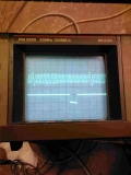
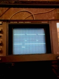
I use an electronic ignition distributor from an MG Metro connected to the M-Squirt hall input circuit (with added pull up resistor of 470ohm). I bended three of the four rotating blades downward so they don’t pas they stationary blade anymore (snapping them off would have disturbed the balance I reckoned) and snapped off three off the stationary posts and connected the M-squirt to the terminal that normally fires the coil. I blocked the centrifugal and vacuum advance. The signals looks very clean at cranking and low RPM and then suddenly starts moving all over the place just before it completely stops, when RPM drops the signal comes back again very clean. Normally the four blades (one for each cyl) are operating in parallel seems to be some kind of hall sensor internally but than quite big. I thought snapping three blades off would not harm the signal strength to much but perhaps I was wrong about that. I will check this further this evening by operating the distributor on a mill and doing some bench testing. I added two pictures of the setup.
|
||||||
 (2)[/url] by [url=https://www.flickr.com/photos/150672766@N03/]Rod Sugden[/url], on Fli) 5988 Posts Member #: 2024 Formally Retired Rural Suffolk |
23rd Dec, 2009 at 08:02:28am
Removing (or bending down) three of the four blades is logical but without knowing why there are (or were !!!) four posts - I would have expected only one for a Hall switch - you may well be right about signal strength.
Edited by Rod S on 23rd Dec, 2009. Schrödinger's cat - so which one am I ??? |
||||||
| Home > A-Series EFI / Injection > MS extra siamese sequential tune (msq) to start with | |||||||
|
|||||||
| Page: |

 (As it was quite a struggle already to get working again with my digital scope after so many years, so much buttons and no user manual
  I won’t expect it to be easy
  ).
).


