| Page: |
| Home > Show Us Yours! > Josh's turbo 1098cc carburetion sucks lets try EFI | |||||||
 (2)[/url] by [url=https://www.flickr.com/photos/150672766@N03/]Rod Sugden[/url], on Fli) 5988 Posts Member #: 2024 Formally Retired Rural Suffolk |
14th Jan, 2014 at 01:15:56pm
On 14th Jan, 2014 Turbo This.. said:
rod do i need to have that Manny signals per rev? plan to use my wheel speed to find out Kph, gear #, fuel efficiency, trip meter if i can? novelty things really Assuming you mean my wheel speed pickups, no, you don't need that many teeth for what you want. I used those ones because (a) they are cheap (common VW/Audi/Seat part from their antilock brake systems), (b) the perfect size to fit inside the rear drums and over the front inner pot joints and, © they will be extremely accurate at low speeds which is what I want for TC. But even for TC, I know people who use 12 or even 6 toothed wheels. On a modern car though, TC usually uses the same sensors as the antilock brakes. On 14th Jan, 2014 Turbo This.. said:
but cant get the temp to work? its that same sender as the coolant one so it uses a restance? rather than output voltage? so since the temp gives an ohms reading what input do i use so ms can read it? Yes, the temperature sensors do not output 0-5V so cannot go straight to an ADC. They need a conditioning circuit which includes a fixed value bias resistor from the 5V (Vref) creating a potential divider so that, as the resistance of the sender varies, the potential divider outputs a varying voltage. I'm not familiar with MS3/MS3X but on an MS2 and or IOx combi, we have to build these circuits ourselves. The circuit is just a copy of the normal CLT or IAT circuit on the V3.0 motherboard (look up the V3.0 mainbord schematics on the MS site and you will see it's only two resistors and two capacitors) The MS3X board may have some included, I'll look later and let you know. However, where it starts to get a bit complicated I'm afraid, is the voltage isn't linear with temperature because the senders are NTC which follows a mathematical curve, so you also have to do a bit of editing of the ini file in TS to calibrate them (well we do in MS2 anyway). Also, I'm not quite sure what you've done with the pressure sender to connect it to an ADC - it will work direct as a 0-5V input but it is good practice to also put in a conditioning circuit to provide some protection to the CPU pin and eliminate noise (that would be a copy of the TPS circuit which is another 0-5V input). Again, I'm not familiar with the MS3X but, with MS2 and or IOx, we build them ourselves, if only for peace of mind. Schrödinger's cat - so which one am I ??? |
||||||
 1767 Posts Member #: 9165 Previously josh4444 Australia, brisbane |
15th Jan, 2014 at 08:08:03am
perhaps there is some where i can wire it up that will take the resistive input?
|
||||||
 (2)[/url] by [url=https://www.flickr.com/photos/150672766@N03/]Rod Sugden[/url], on Fli) 5988 Posts Member #: 2024 Formally Retired Rural Suffolk |
15th Jan, 2014 at 08:30:40am
On 15th Jan, 2014 Turbo This.. said:
perhaps there is some where i can wire it up that will take the resistive input? or i might have to find a temp sender for use in oil that gives 0-5v not sure i want to mess with the pcb unless its fool proof You're in luck.... I said yesterday I wasn't familiar with the MS3/MS3X but they might have included some pre-built ADC conditioning circuits (as an advance on the MS2 where we have to build our own) and they have, see here, http://www.msextra.com/doc/ms3/hardware.html#ms3xjps Big red box in the middle shows they have included spaces to install the bias resistor for temperature sensor (ie, resistive, not 0-5V) inputs. So a simple soldering job. And the fact they've included the circuits most likely means the ini file should already have all the right text in it to deal with the calibration (and won't need editing like with an MS2/IOx setup). As for your conrod bolts, I haven't a clue apart from, maybe, are they the right conrods for that block ? EDIT - typo and added a bit. Edited by Rod S on 15th Jan, 2014. Schrödinger's cat - so which one am I ??? |
||||||
 1767 Posts Member #: 9165 Previously josh4444 Australia, brisbane |
15th Jan, 2014 at 09:09:46am
brilliant so ill need to get the 2.49K resistors from the local electronics store tomorrow i can handle drop in n solder jobs haha |
||||||
 (2)[/url] by [url=https://www.flickr.com/photos/150672766@N03/]Rod Sugden[/url], on Fli) 5988 Posts Member #: 2024 Formally Retired Rural Suffolk |
15th Jan, 2014 at 09:24:36am
For the resistors get 1% tolerance metal film ones if you can (not the more common 5% or 10% carbon film ones). These are what are used on the V3.0 mainboard for the temperature bias resistors, the 1% means your reading will be much more accurate and metal films don't drift in value as much when their surronding temperature changes.
Schrödinger's cat - so which one am I ??? |
||||||
 1767 Posts Member #: 9165 Previously josh4444 Australia, brisbane |
15th Jan, 2014 at 09:32:31am
ok will see if i can get the good 1% ones cheers for the heads up
|
||||||
 1767 Posts Member #: 9165 Previously josh4444 Australia, brisbane |
19th Jan, 2014 at 08:00:18am
well ive plumbed the fuel system up and feed up with it.. twin tanks are a pain if they are not genuine!!
|
||||||
 1767 Posts Member #: 9165 Previously josh4444 Australia, brisbane |
25th Jan, 2014 at 01:30:26am
rod ive gotten some 2.4k ones as that was as all they had will the 0.09k be much difference? this is the actual measured value
|
||||||
 (2)[/url] by [url=https://www.flickr.com/photos/150672766@N03/]Rod Sugden[/url], on Fli) 5988 Posts Member #: 2024 Formally Retired Rural Suffolk |
25th Jan, 2014 at 05:36:14pm
Josh,
Edited by Rod S on 25th Jan, 2014. Schrödinger's cat - so which one am I ??? |
||||||
 1767 Posts Member #: 9165 Previously josh4444 Australia, brisbane |
25th Jan, 2014 at 10:13:10pm
cheers rod your a top bloke appreciate it
|
||||||
 (2)[/url] by [url=https://www.flickr.com/photos/150672766@N03/]Rod Sugden[/url], on Fli) 5988 Posts Member #: 2024 Formally Retired Rural Suffolk |
26th Jan, 2014 at 08:53:43am
Josh, spreadsheet sent by email.
Schrödinger's cat - so which one am I ??? |
||||||
 1767 Posts Member #: 9165 Previously josh4444 Australia, brisbane |
4th Feb, 2014 at 10:30:20am
nothing really happening as work is flat to the boards...
|
||||||
|
614 Posts Member #: 2153 Post Whore kings langley |
4th Feb, 2014 at 07:58:55pm
I have seen a groove machined into rods that directs oil up at the piston, there is a pic on this link
Speeding is like masturbating, everyone does it, but not all of us film it and put it on the internet
|
||||||
 1767 Posts Member #: 9165 Previously josh4444 Australia, brisbane |
9th Feb, 2014 at 04:53:10am
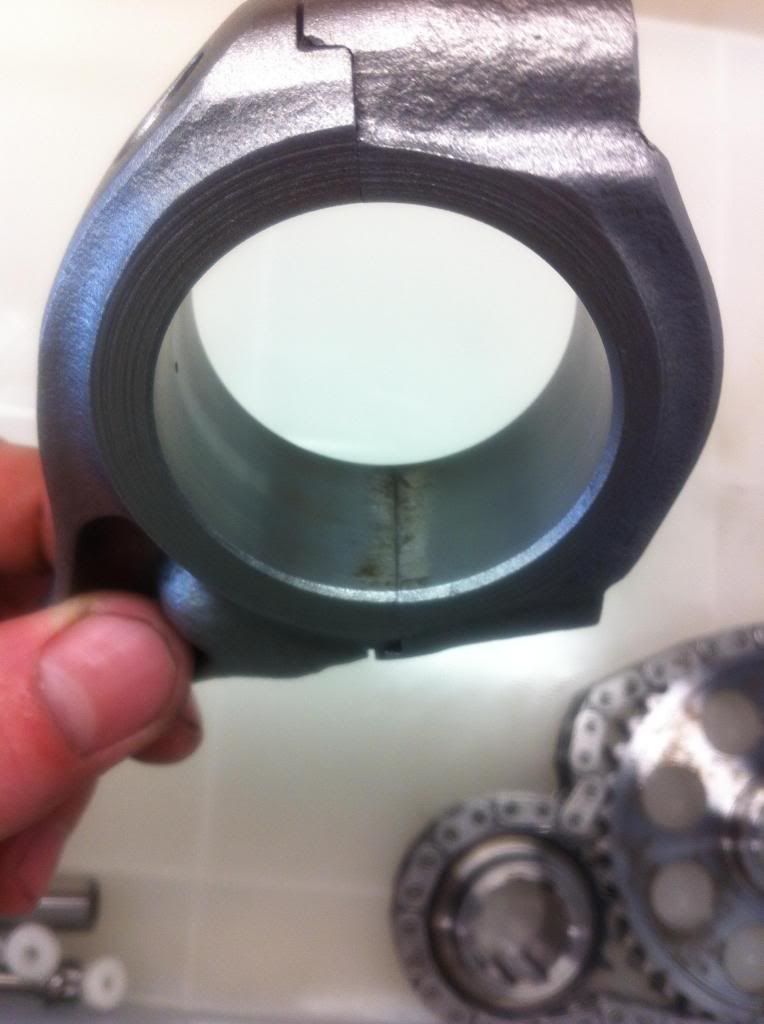
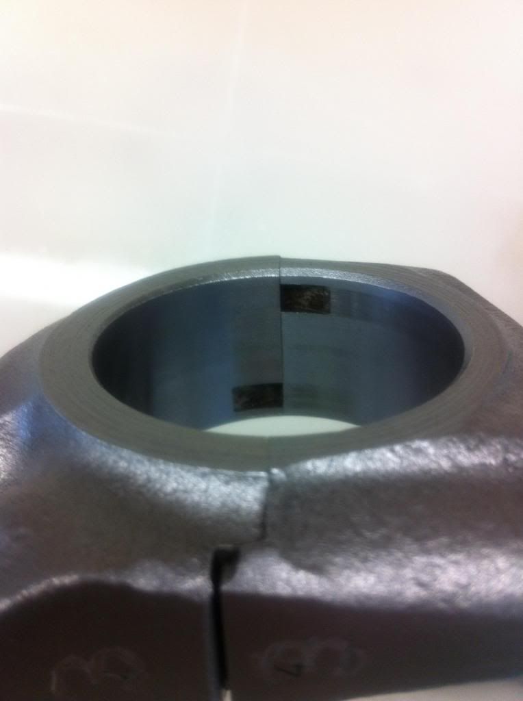
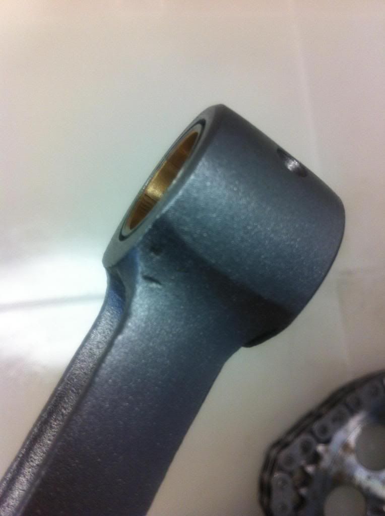
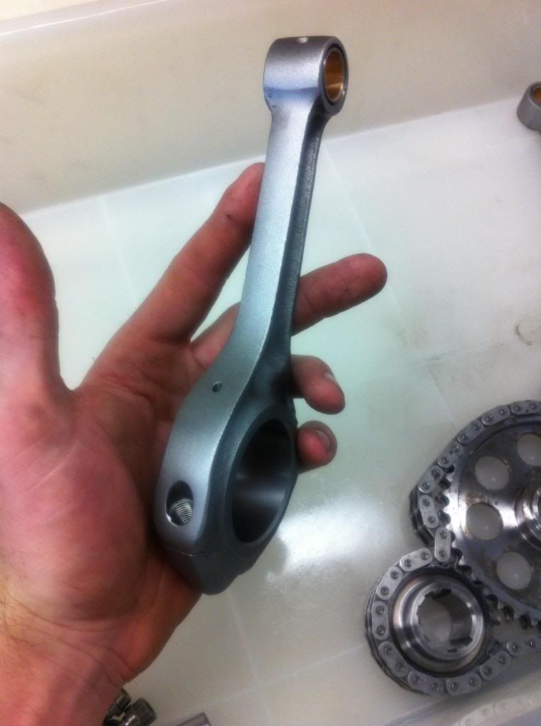
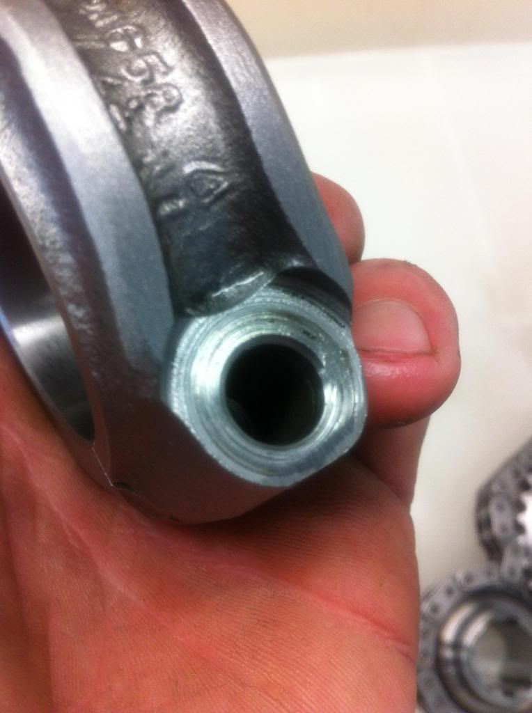
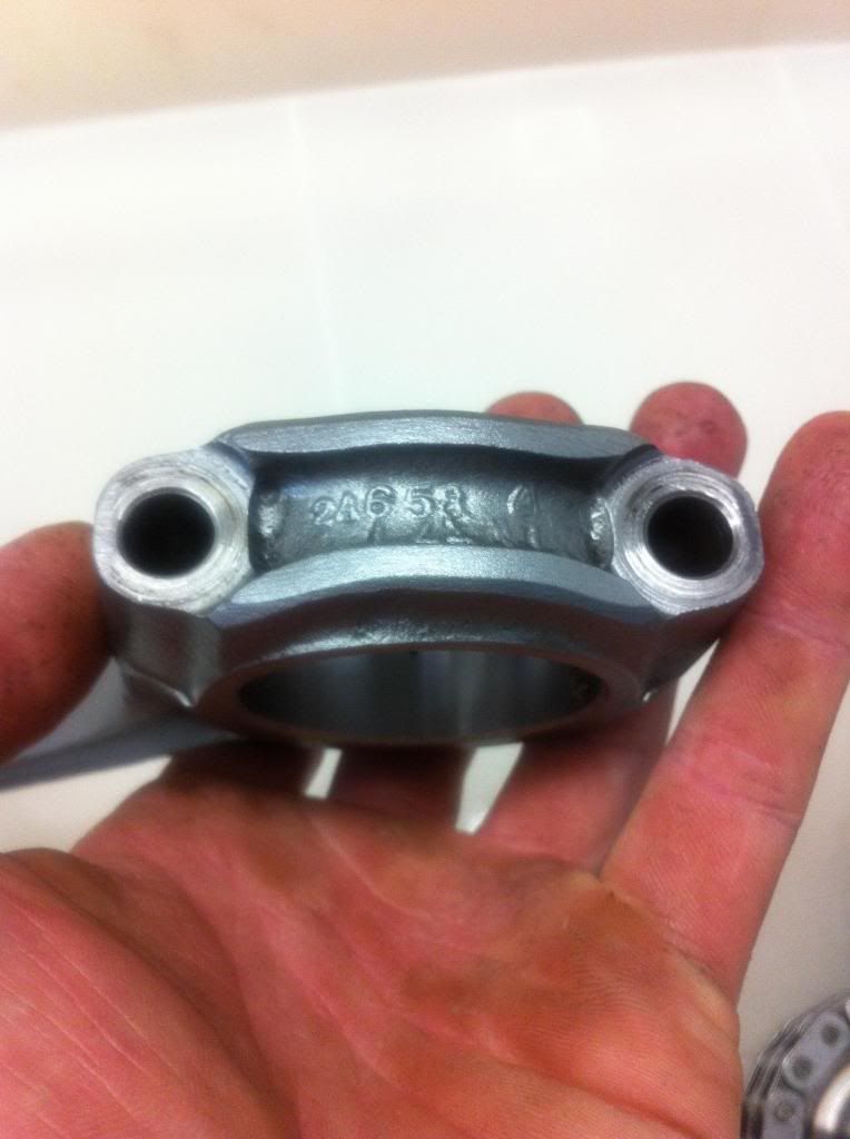
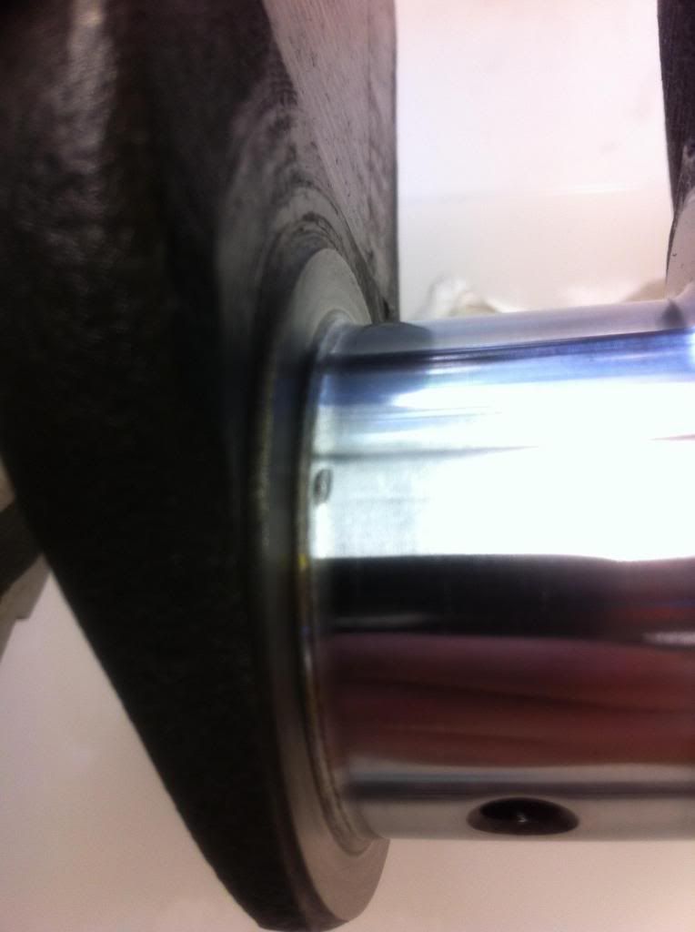
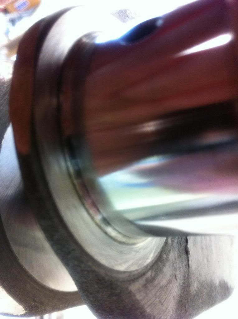
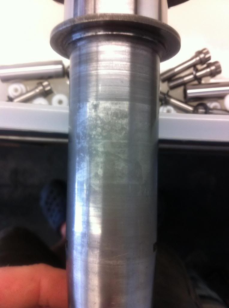
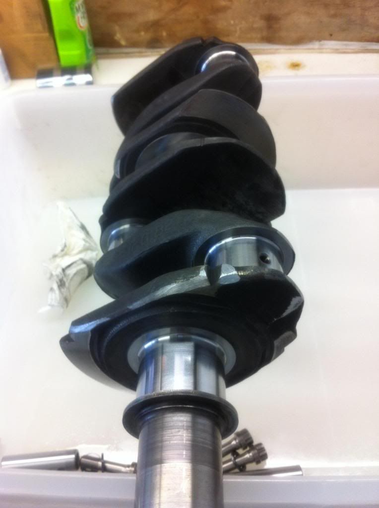
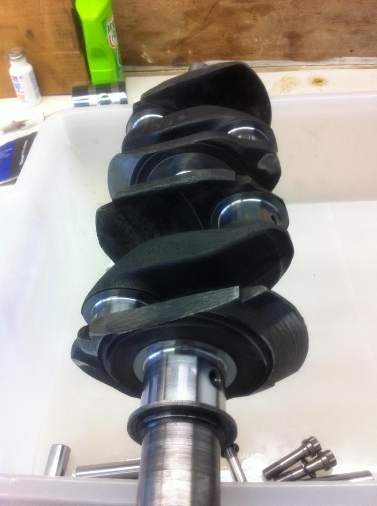
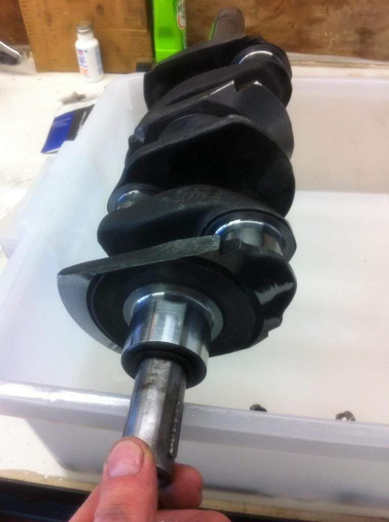
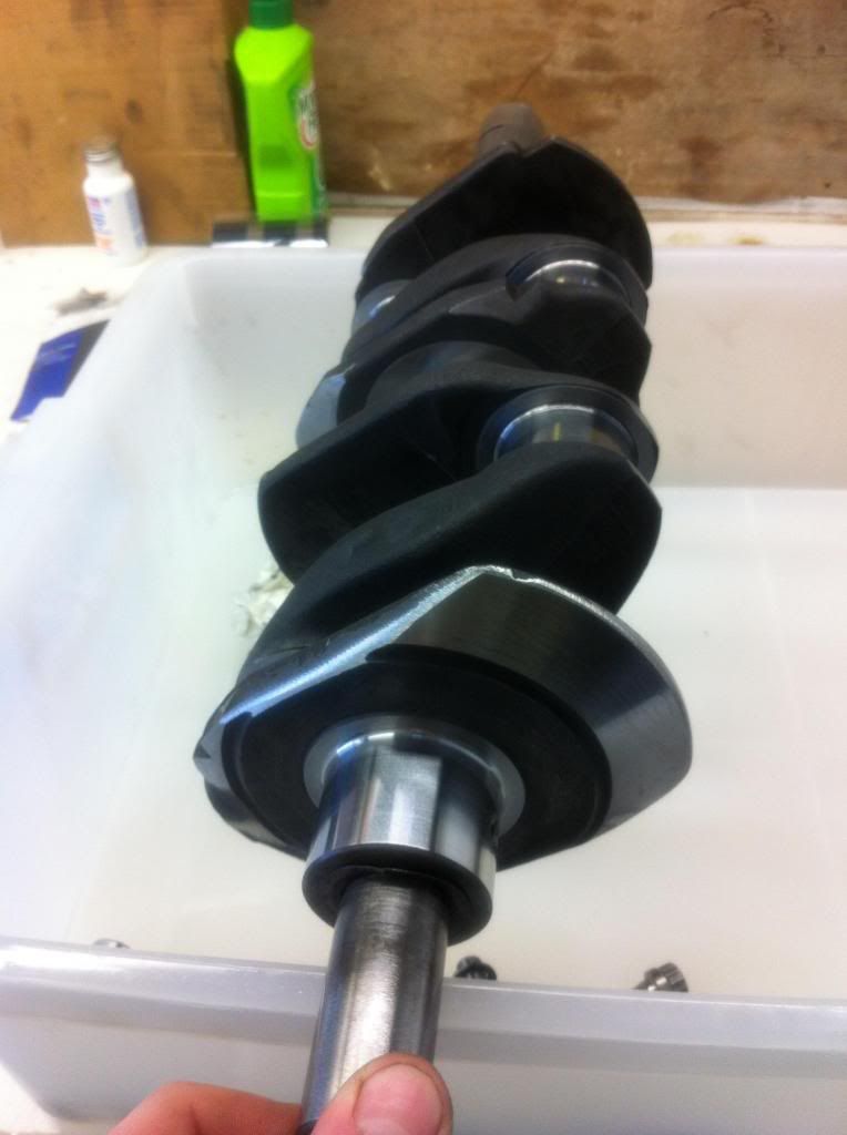
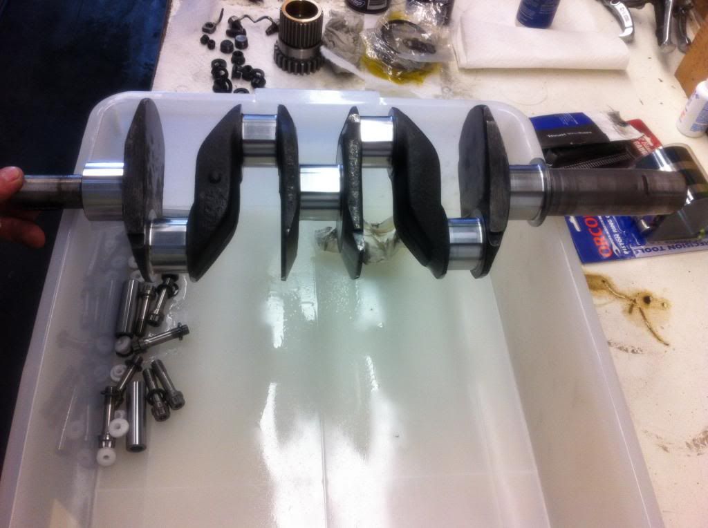
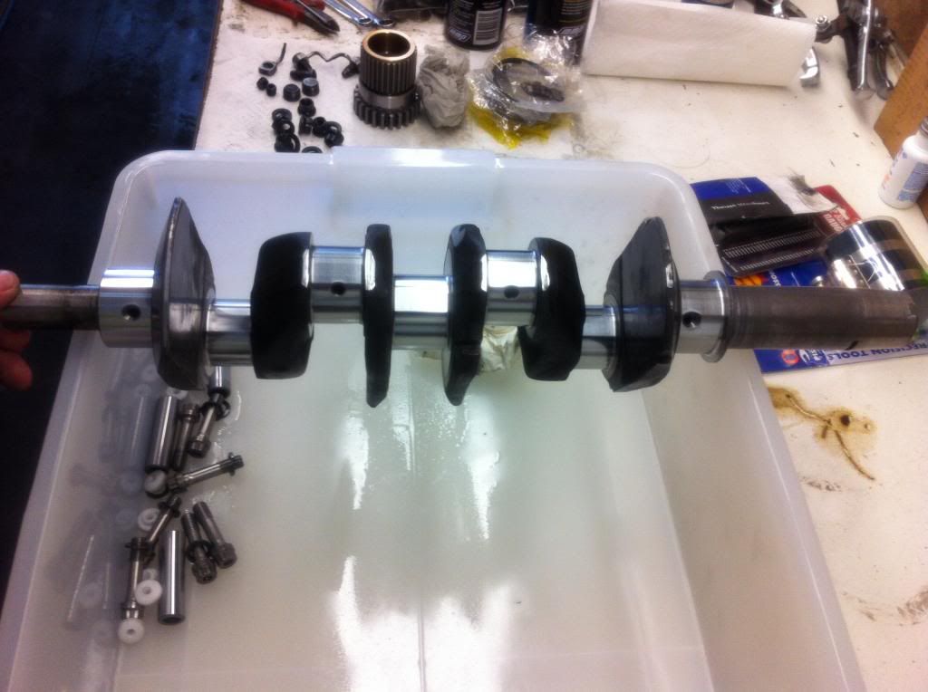
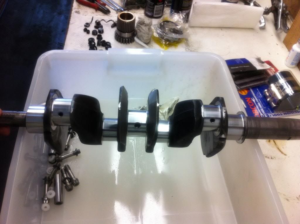
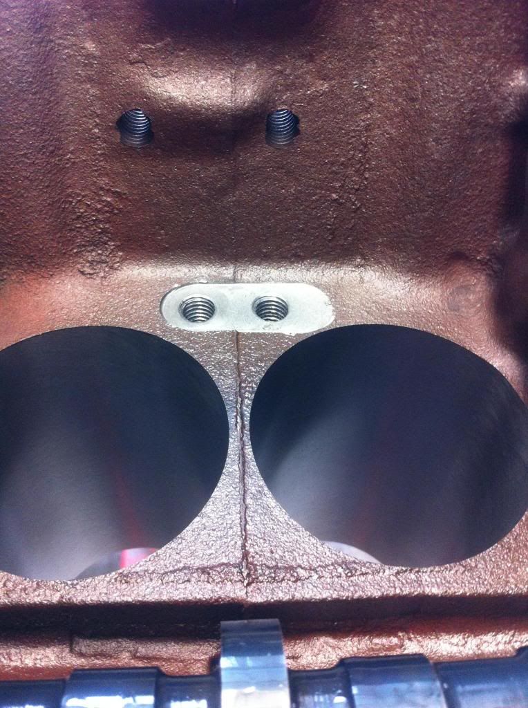
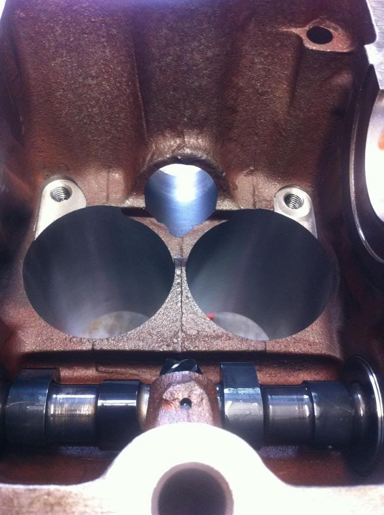
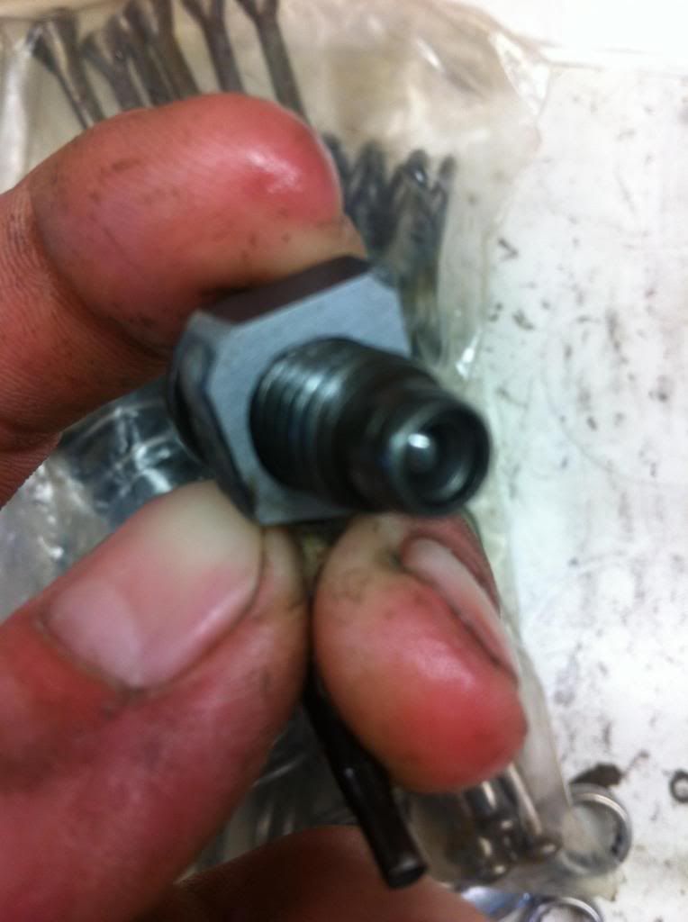
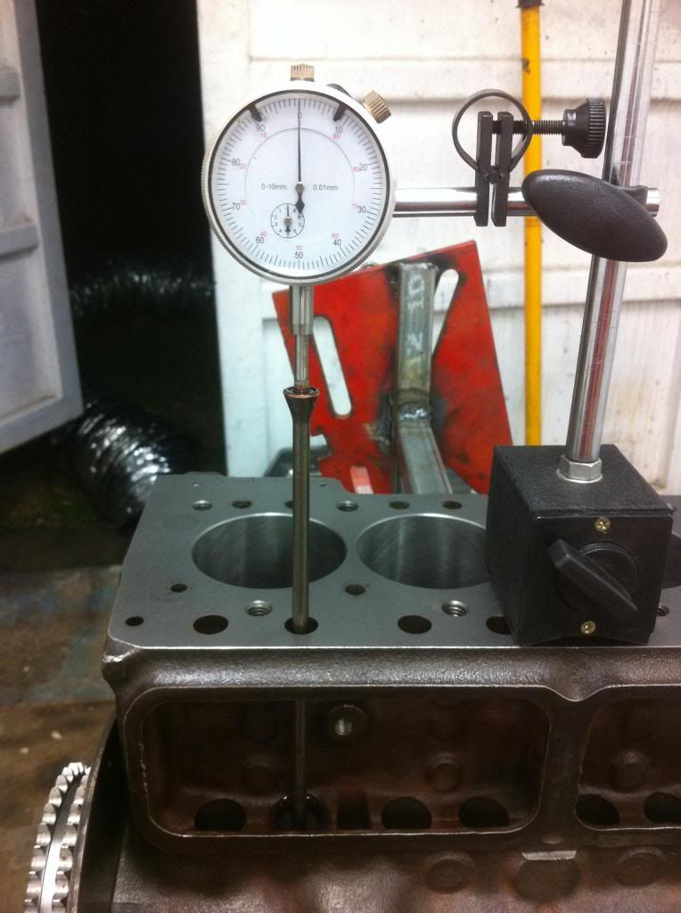
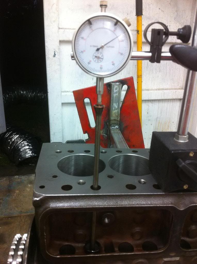
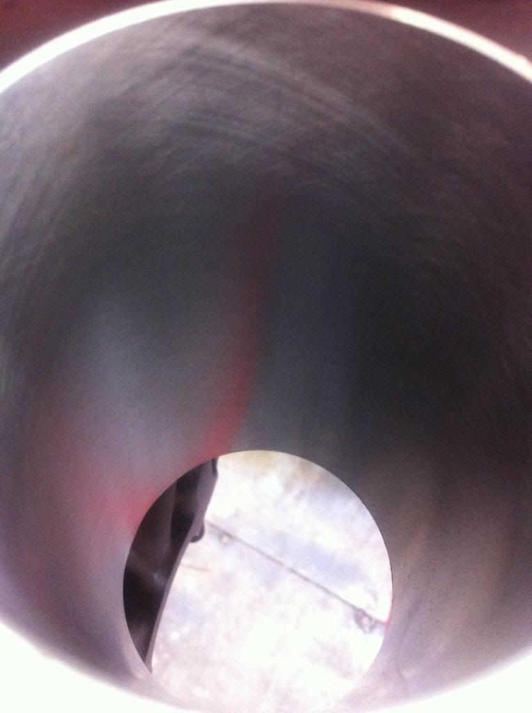
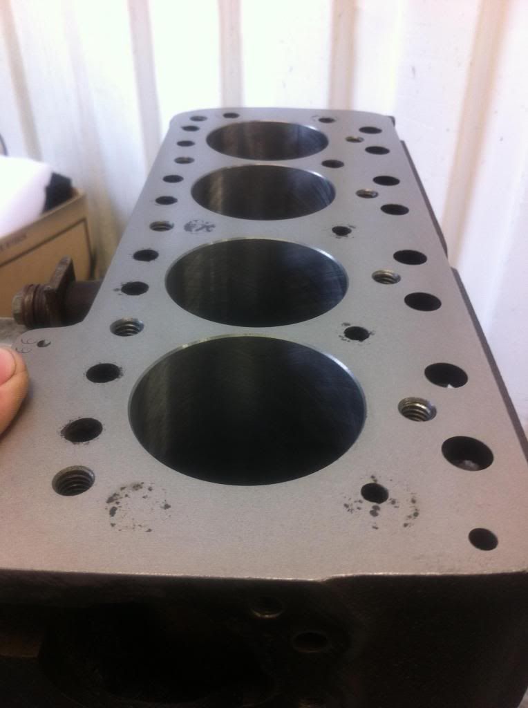
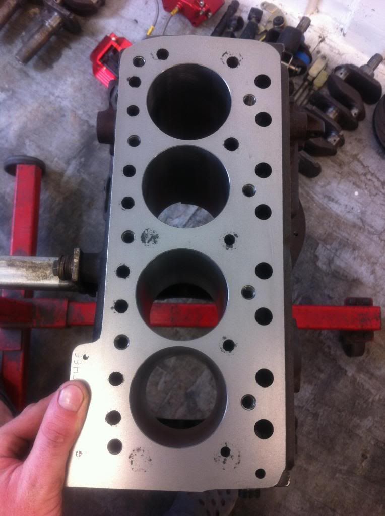
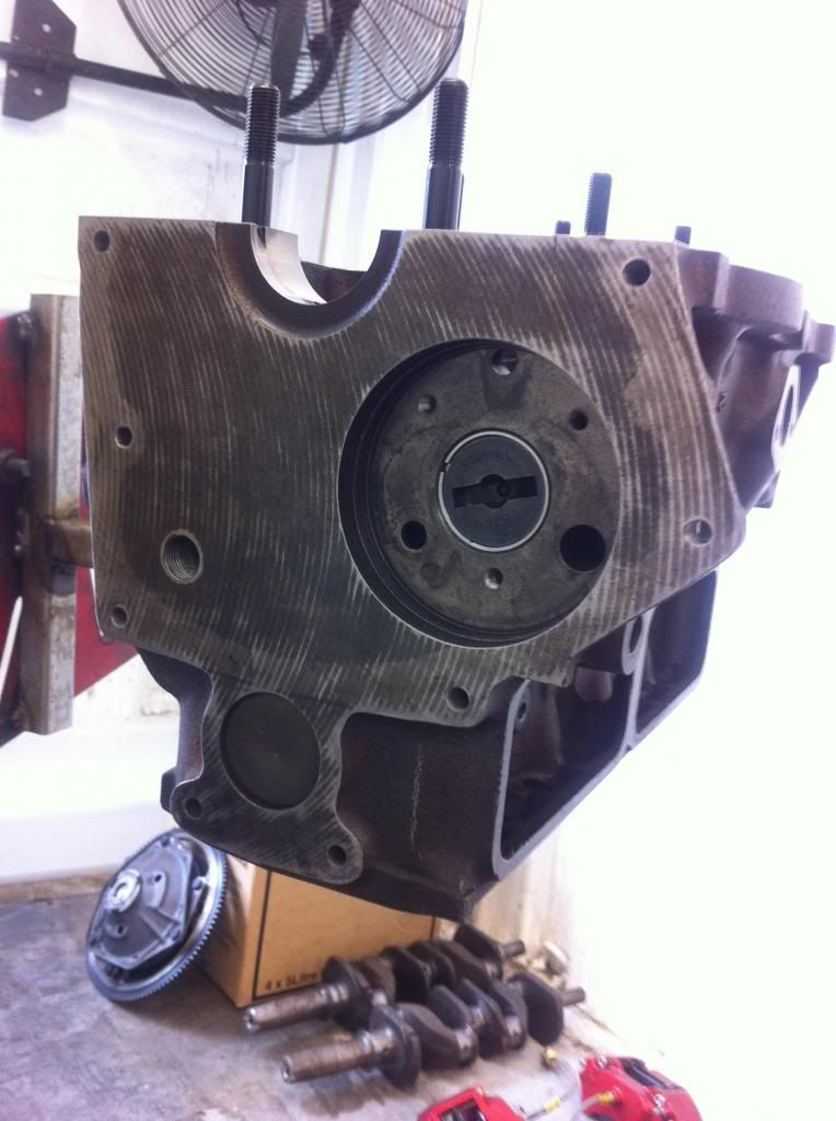
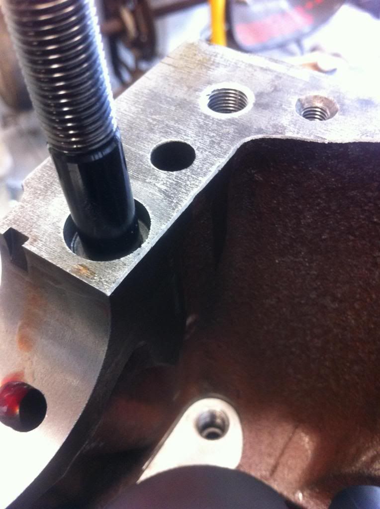
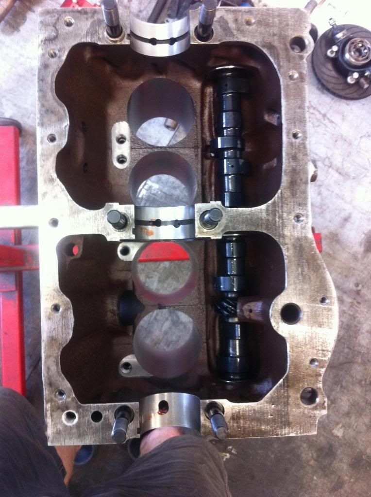
So ive picked up my parts from the shop at this stage ive got some questions regarding the shops work... ive given most parts a "first clean"
|
||||||
 1767 Posts Member #: 9165 Previously josh4444 Australia, brisbane |
9th Feb, 2014 at 08:51:16am
well ive worked out the primary gear problem it was burs on the "c" washer grove stopping it sliding on
|
||||||
 (2)[/url] by [url=https://www.flickr.com/photos/150672766@N03/]Rod Sugden[/url], on Fli) 5988 Posts Member #: 2024 Formally Retired Rural Suffolk |
9th Feb, 2014 at 09:25:16am
I'll just give my views on a few of the bits you've mentioned, not everything...
On 9th Feb, 2014 Turbo This.. said:
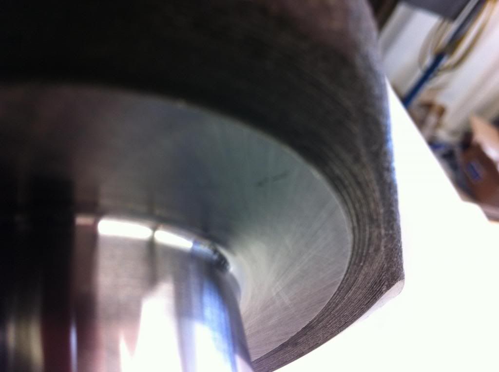
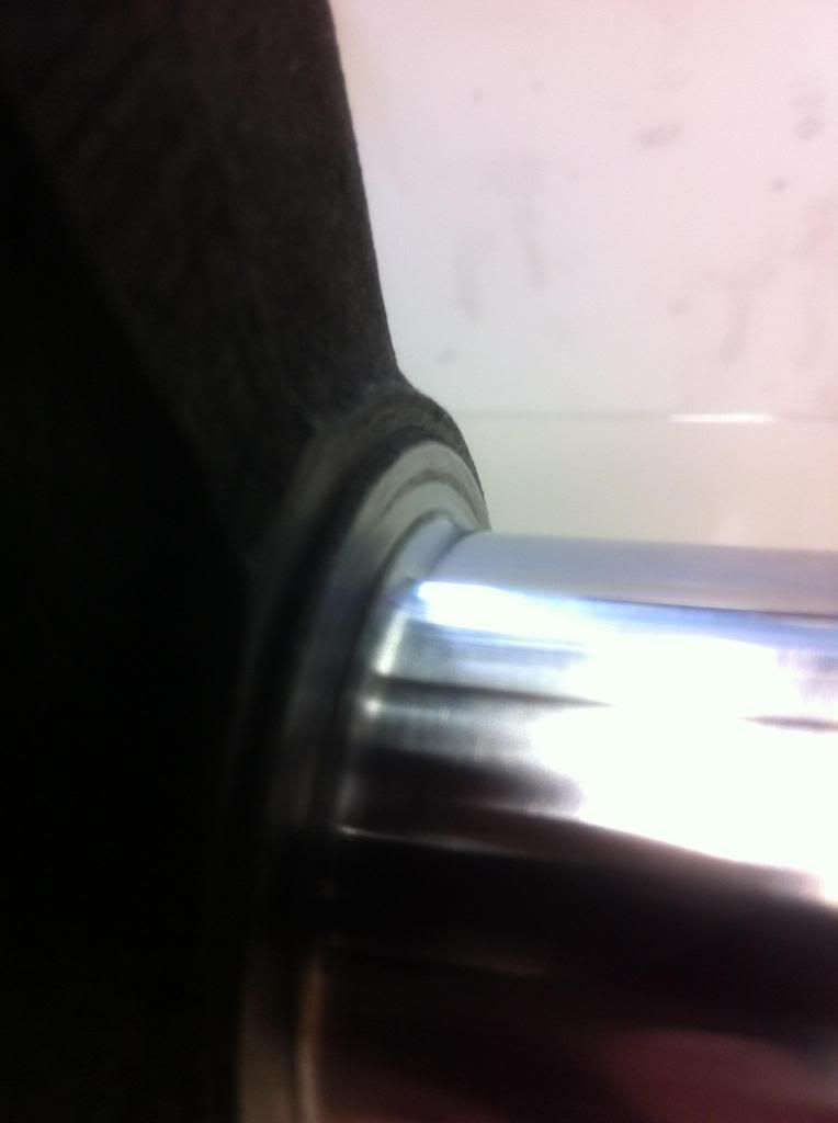
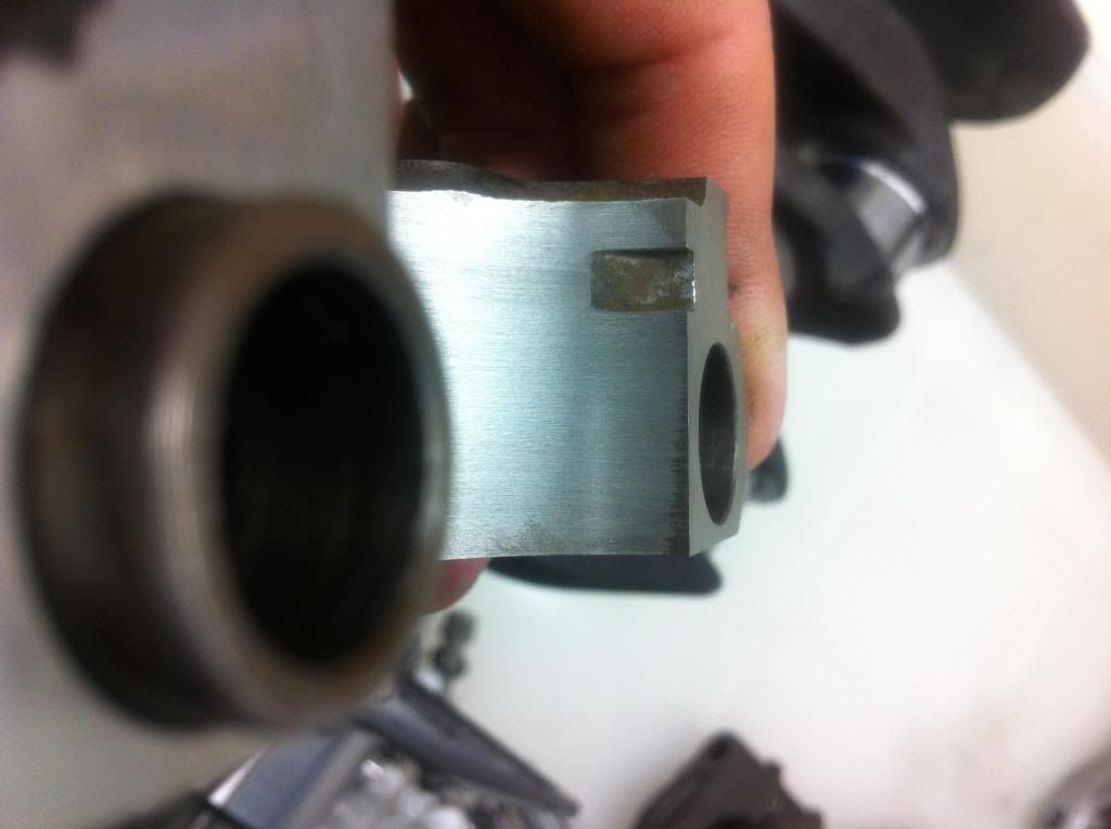
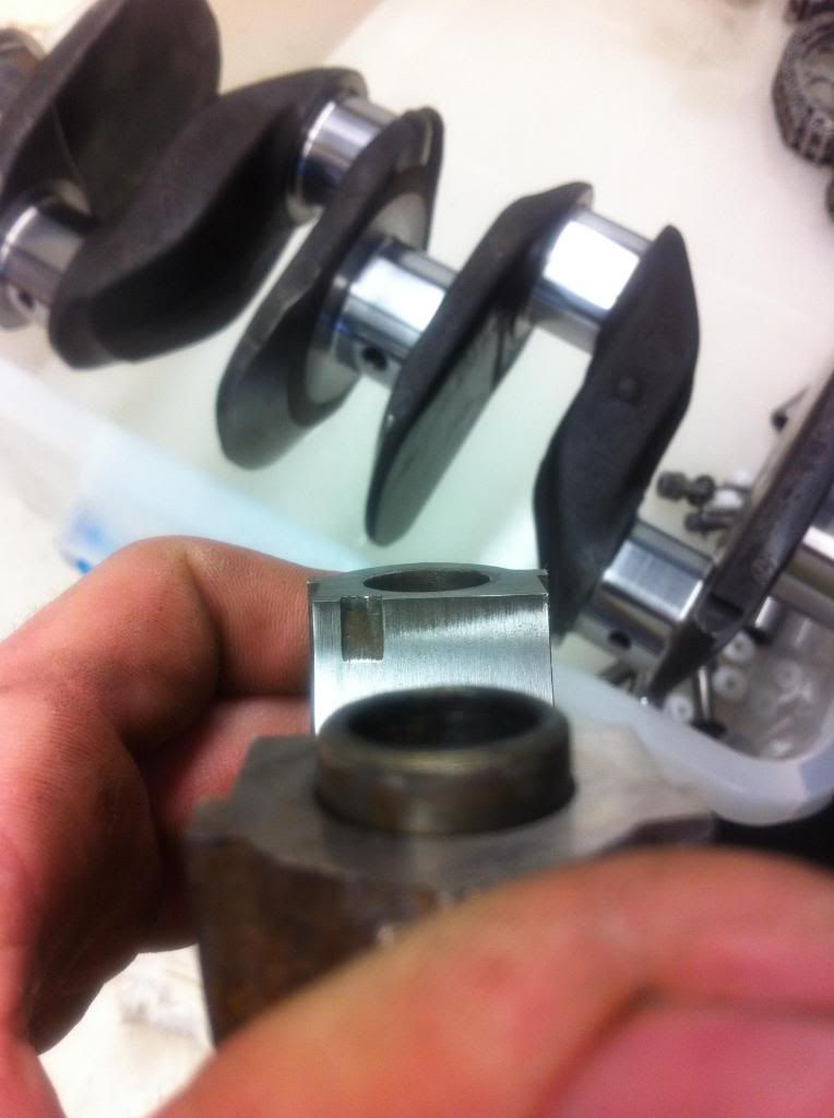
the rods i see that the shot penning has been done on the "thrust" face? is that surface supost to be like a journal and machined all nice? I certainly wouldn't have done any "peening" there. I would have masked that area off (as simply as two large washers covering the "bearing" faces held in place with a bolt through the big end). Without seeing how "rough" it is (photos really don't show enough detail) it's hard to say how it will affect the oil film in that area. At least on a small bore engine there is very little side load there. On 9th Feb, 2014 Turbo This.. said:
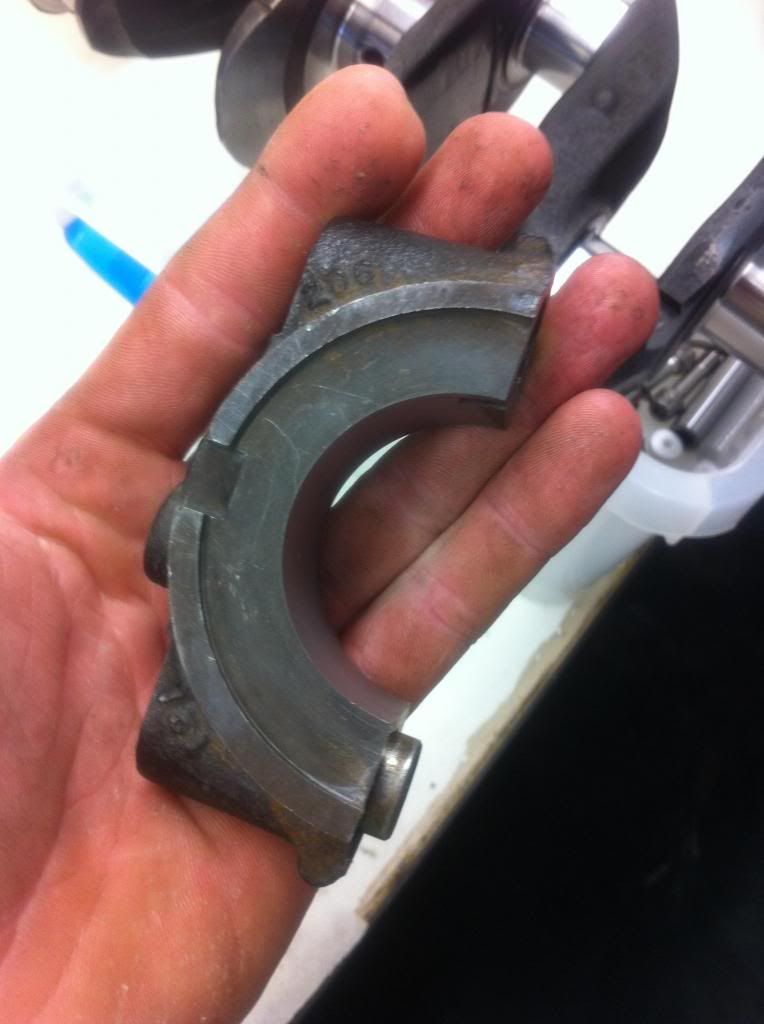
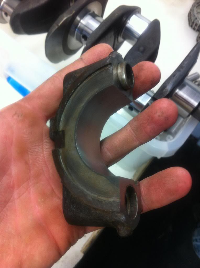
for what ever reason ive not been given the "sized" bearings that are numbered for placement jurnal for jurnal and top for bottom halfs i do rember the call to say this crank is 10 or 20 not the 30 you have supliyed so do you want us to get bearings or will you supply them and i said you guys can get them also not sure if i said get the grove/plain type or not? anyway ill see to this on monday.. There is no reason for the bearing shells to be numbered for individual rods/journals unless, in very extreme circumstances, they had reground one journal a different size to the others. They should all be identical at a "standard" undersize. I can't remember if the small bore top and bottom halves are different but if so, it will be obvious. As for grooved/plain main bearings, I thought that late change in design (A+) only affected the large bore engines (but I may be wrong). On 9th Feb, 2014 Turbo This.. said:
i want to do the idot checks with plaster gauge and what ever else i can to check the shops work... Plastigauge.... Yes, I would most definately use it on all 7 bearings looking at the overall quality of their work. On 9th Feb, 2014 Turbo This.. said:
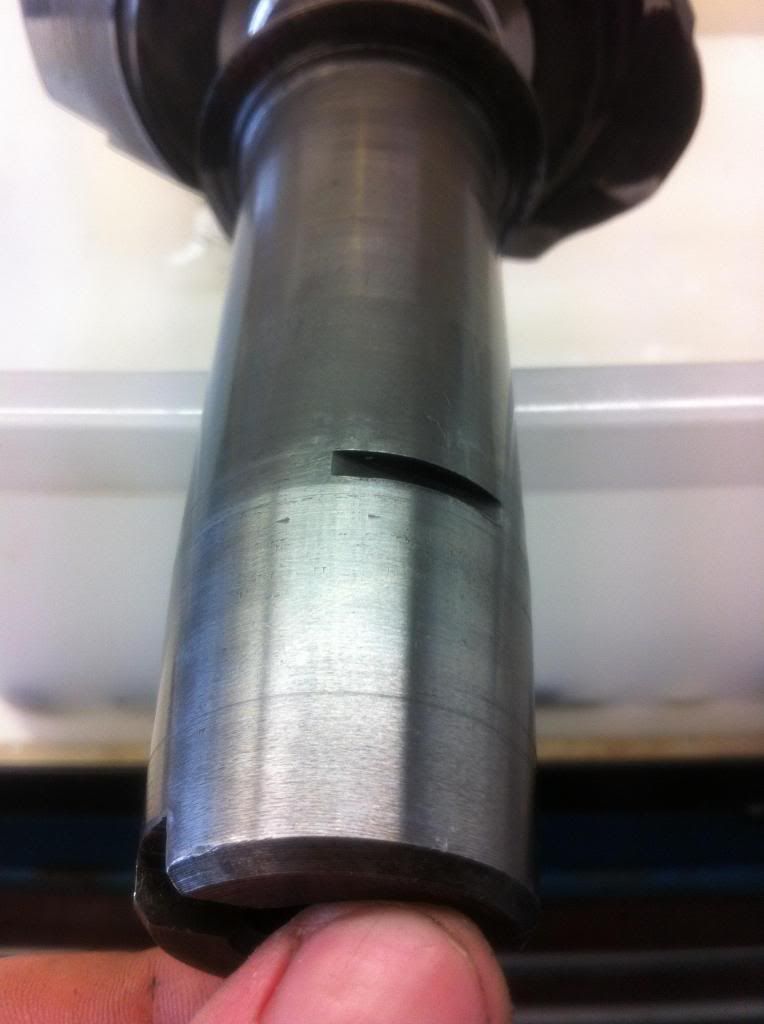
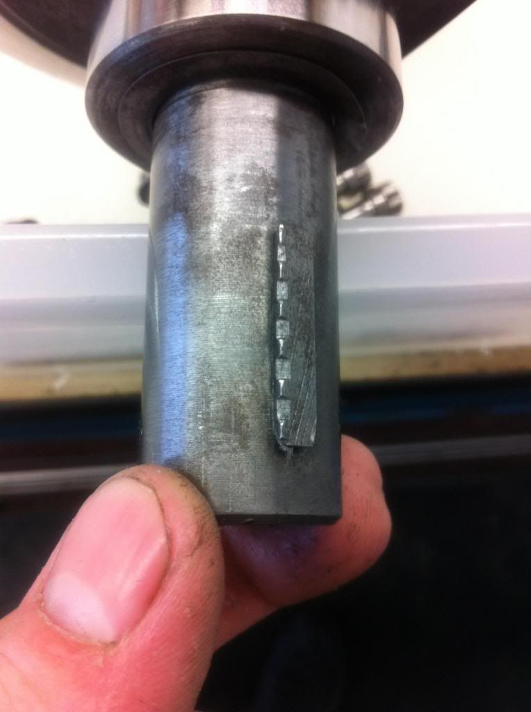
not sure on this key ether looks as someone has punched it to fatten it up hahah It's certainly been butchered for some reason. I would find out why before going any further. Does the pulley actually slide over it ? If it does with that damage, then they did it to hide a worn keyway in the pulley. If it doesn't they did it to hide a worn keyslot in the crank. The correct solution in both cases would be to mill the slots out for an oversize key. If neither are worn, they are just total animals and you need a new key and you need to check all their other work VERY carefully. On 9th Feb, 2014 Turbo This.. said:
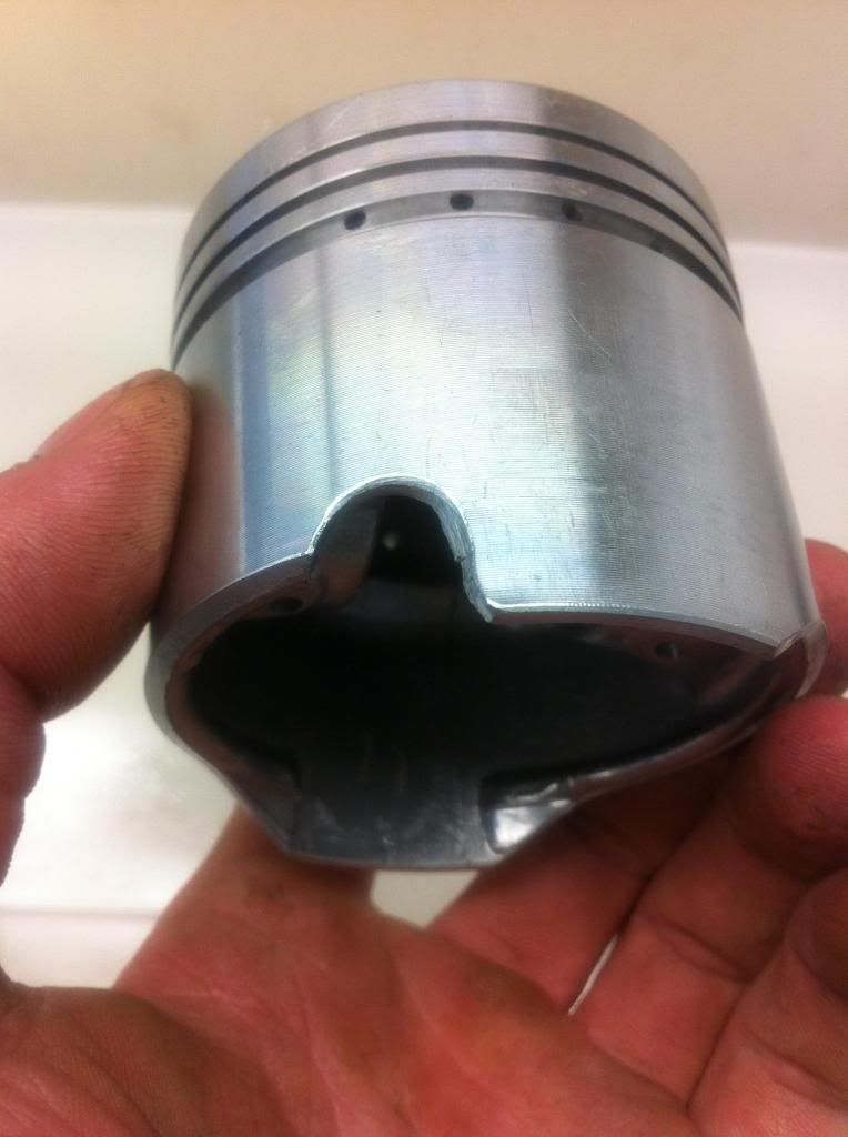
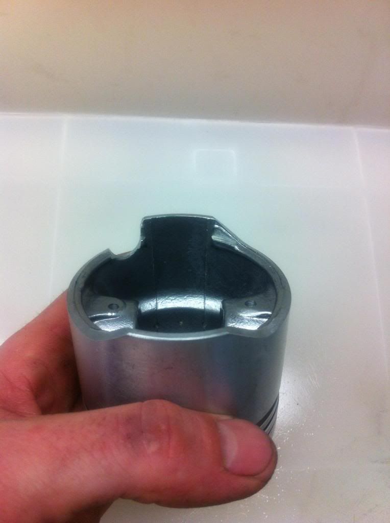
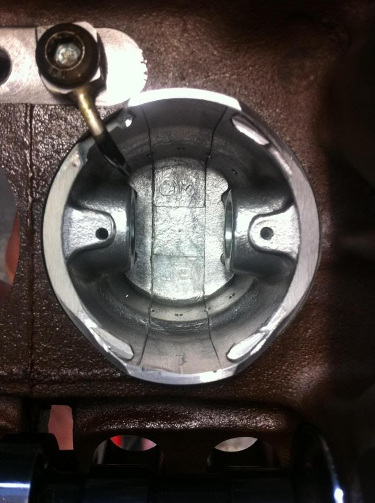
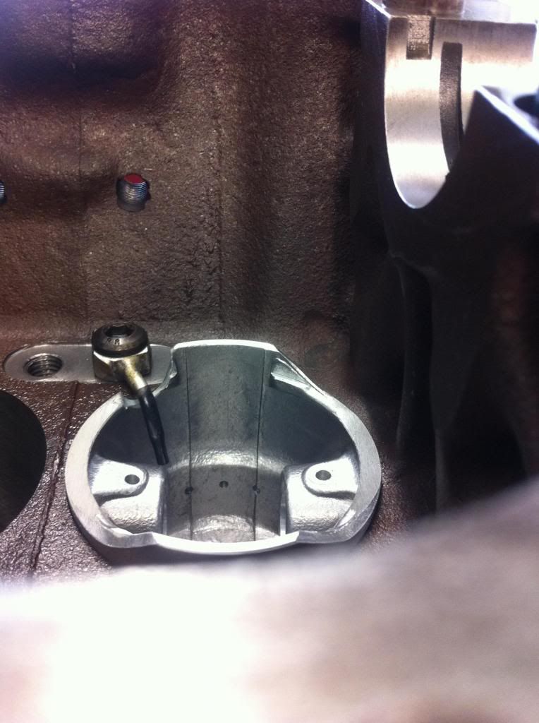
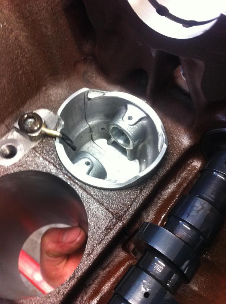
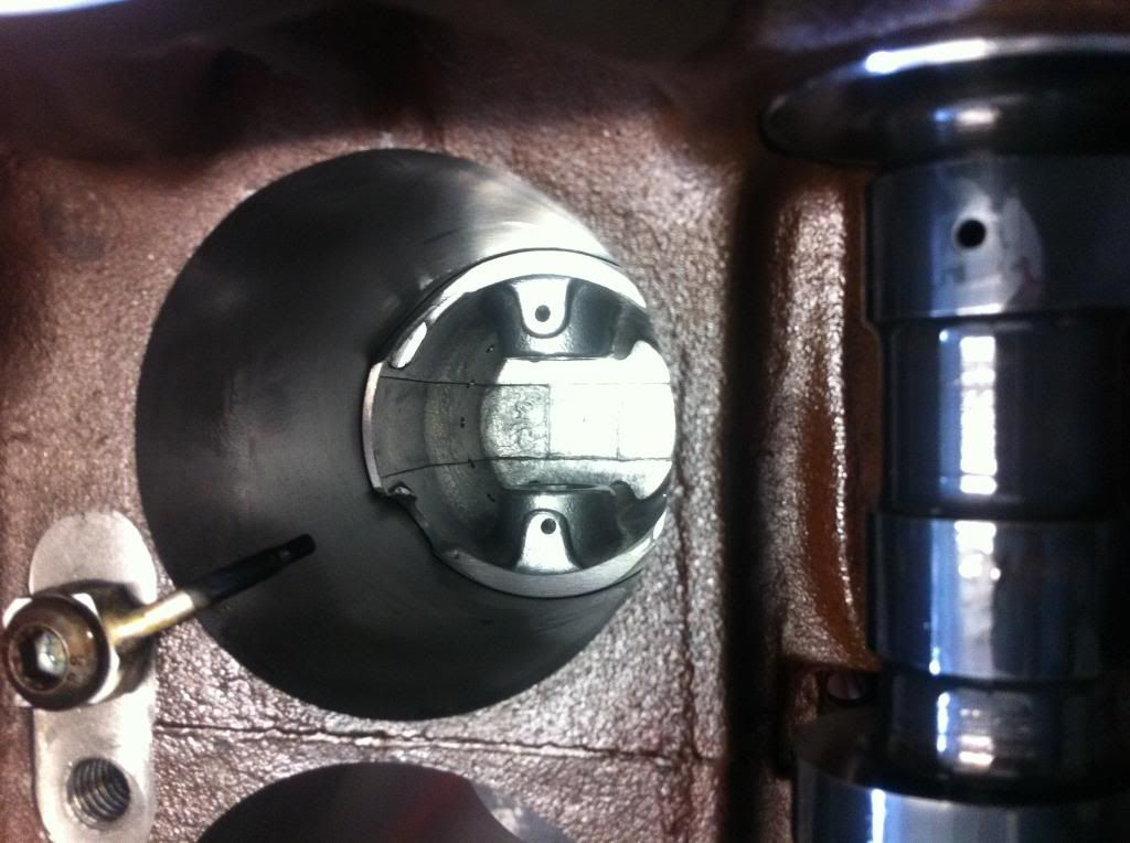
pistons learanced for jets they where ballanced each for each after the fack... Was it really necissary to butcher them like that ? I know it's a long stroke crank but do the pistons really come that far down ? If it really was necissary I would have expected it to have been done on a mill - that looks like a die grinder and/or a bastard file, it's not even been blended smooth. On 9th Feb, 2014 Turbo This.. said:
not real sure on the angle of spray think ill mock it all up and pump kero throw it to see where they actualy hit also where it the best place to shoot for on the pistion and stroke? tdc bdc mid way? center of crown? Bear in mind if you aim for the centre of the crown's underside, a lot of the time it will be shielded by the little end bearing lump of metal at the top of the conrod. So when you mock it up, do so with the piston(s), conrod(s) and crank installed and the see where you have to aim to actually hit the crown as the conrod goes up/down. On the only OEM install I've seen (which used a spraybar rather than individual jets) the oil was directed towards the underside of the crown between the little end bearing and the piston wall (so it allways hits the crown). Schrödinger's cat - so which one am I ??? |
||||||
 (2)[/url] by [url=https://www.flickr.com/photos/150672766@N03/]Rod Sugden[/url], on Fli) 5988 Posts Member #: 2024 Formally Retired Rural Suffolk |
9th Feb, 2014 at 09:45:26am
I should probably add I would have explored all other possibilities if the pistons really do come that far down (before butchering the pistons) to get the jets lower.
Schrödinger's cat - so which one am I ??? |
||||||
 1767 Posts Member #: 9165 Previously josh4444 Australia, brisbane |
9th Feb, 2014 at 10:24:05am
hmmm, so its not just myself that is somewhat disappointed by the work then.. hopefully the shop dose the right thing as addresses my concerns with something decant rather than yeah she will be right.
|
||||||
 (2)[/url] by [url=https://www.flickr.com/photos/150672766@N03/]Rod Sugden[/url], on Fli) 5988 Posts Member #: 2024 Formally Retired Rural Suffolk |
9th Feb, 2014 at 11:16:29am
On 9th Feb, 2014 Turbo This.. said:
in order to get the best oil clearance possible dont you install the bearings and then bore gauge them on at a bunch of places then pick and chose bearing shells to get the best fit up? Personally, I wouldn't, not on a normal build on a normal engine as the manufacturing tolerances of the shells nowadays is so good that all eight big end half shells (for example) should be identical thicknesses. And the tolerance on the rod bores from the factory should be equally as good. Same logic for main bearings. If, for some reason one or the other weren't, you would pick it up when you plastigauge. BUT... some of those photos imply you have had the rod big ends re-worked (if so I can't remember why) and the main bearings too ? So it depends on the quality of their sizing if/when they were re-worked. If they are back to factory size and all identical again, there should be no reason to swap shells around but if they are not quite as they should be, there might be some minor gains by trial and error swapping shells but, as the shell tolerances will be so good, the gains would be minor. First thing I would do, bearing in mind the quality of some of their other work, is measure the internal diameters of the rod ends and main bearings (without shells) and check they are all the size they should be. And measure all the crank journals to make sure they are identical on the big ends and identical on the mains. Schrödinger's cat - so which one am I ??? |
||||||
 1767 Posts Member #: 9165 Previously josh4444 Australia, brisbane |
9th Feb, 2014 at 07:37:33pm
ok must jet be the really high end stuff that they do like that..
|
||||||
 1767 Posts Member #: 9165 Previously josh4444 Australia, brisbane |
10th Feb, 2014 at 10:56:45am
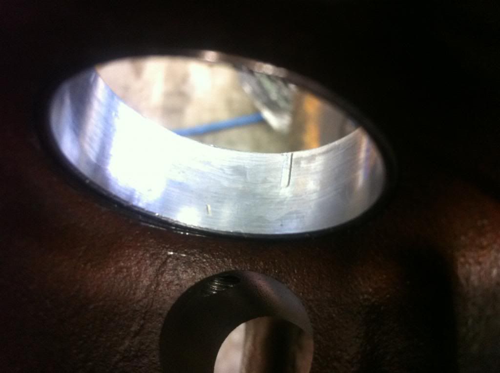
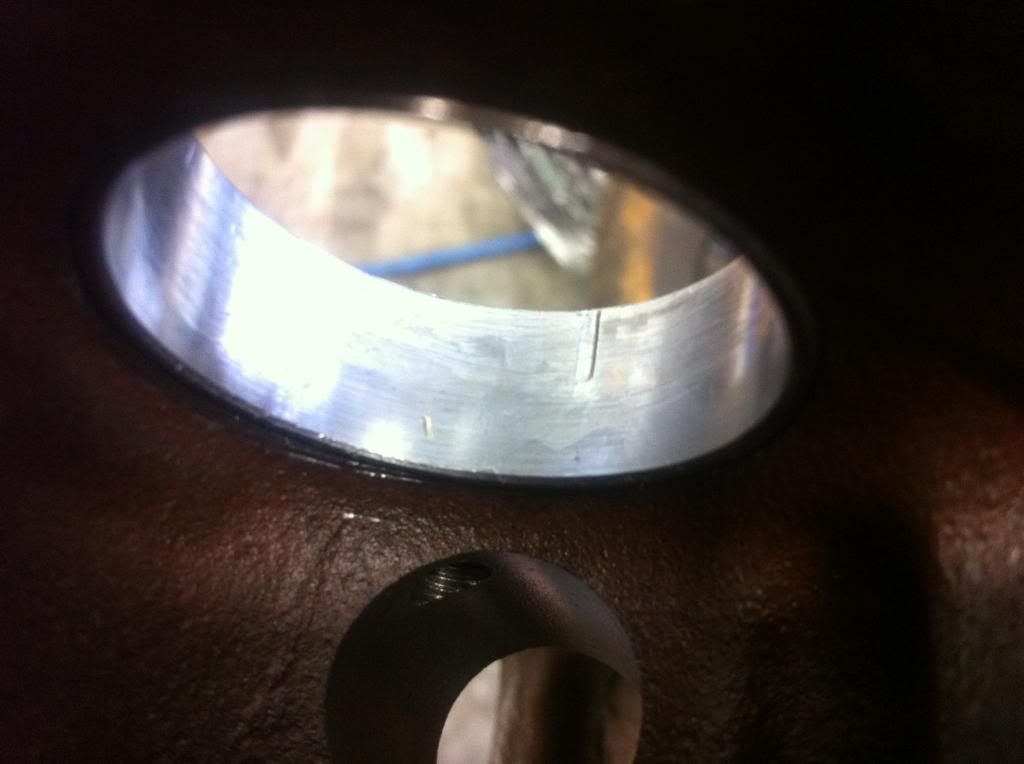
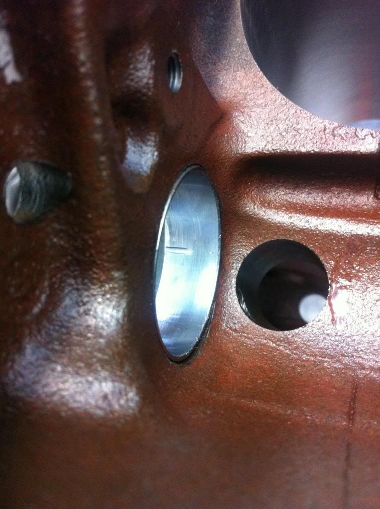
picked up my bearings this arvo and well the shells seem ok but the thrusts lock it up when niped up with a spanner not much tnesion at all... at this point i feel like giveing up with the "quality" of there work
Edited by Turbo This.. on 10th Feb, 2014. |
||||||
 (2)[/url] by [url=https://www.flickr.com/photos/150672766@N03/]Rod Sugden[/url], on Fli) 5988 Posts Member #: 2024 Formally Retired Rural Suffolk |
10th Feb, 2014 at 11:08:57am
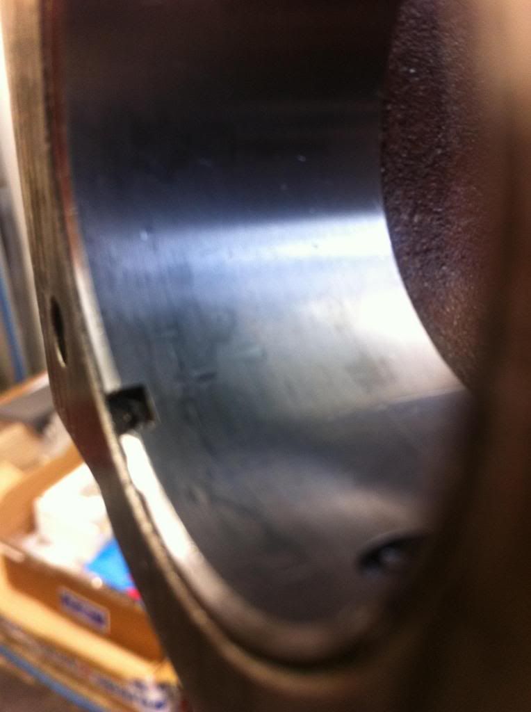
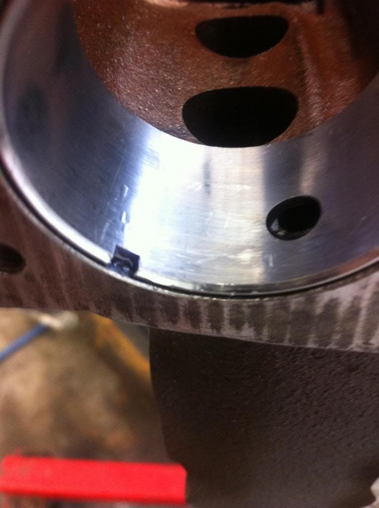
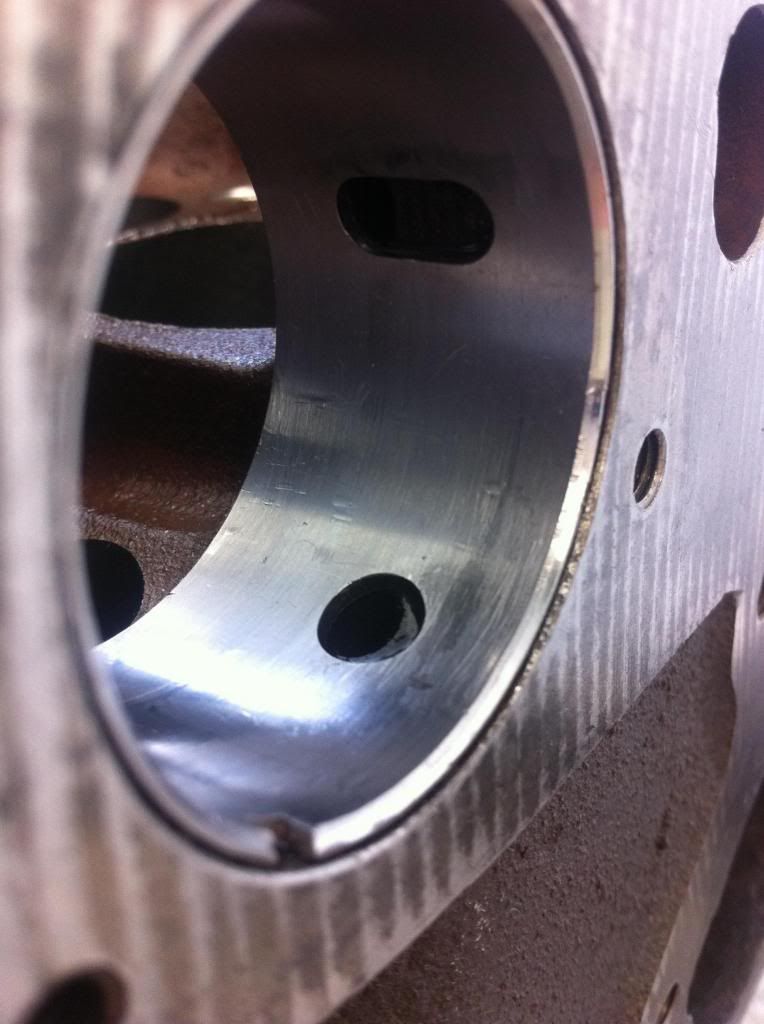
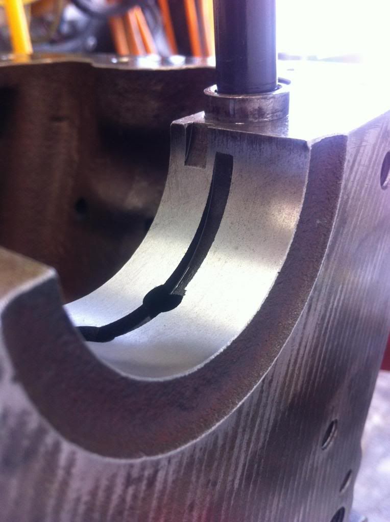
If you had the main bearing caps mating surfaces refaced and the whole lot line bored/honed - which it looks as if you did (but I'm not sure) - the photos don't show any work on the bit where the thrusts sit.
Schrödinger's cat - so which one am I ??? |
||||||
 1767 Posts Member #: 9165 Previously josh4444 Australia, brisbane |
10th Feb, 2014 at 11:18:24am
ahh will do hadnt thought of that
On 10th Feb, 2014 Rod S said:
If you had the main bearing caps mating surfaces refaced and the whole lot line bored/honed - which it looks as if you did (but I'm not sure) - the photos don't show any work on the bit where the thrusts sit. What that could mean is that, although the centre main bearing housing is round again, the recess the thrust washers sit in won't be. It will have lost height. The thrust washers are normally a pretty loose fit (vertically) in the recess but may now be getting nipped up and pushed outwards as you tighten the cap. Assemble the centre main cap reasonably tight (no need for full torque) - with no crank and no main bearings - and just see if the thrust washers actually fit in their recesses as pairs with a bit of free movement up and down. |
||||||
 1767 Posts Member #: 9165 Previously josh4444 Australia, brisbane |
14th Feb, 2014 at 10:31:35am
once again the experience and knowledge on this forum pays off, rod was right in saying the thrusts might be tight..
|
||||||
 54 Posts Member #: 2819 Advanced Member south east, Melbourne, Victoria, Australia |
14th Feb, 2014 at 08:23:24pm
do what rod said about the thrust face on the main caps. on your conrods the part that didnt clean up is normal, sometimes you can put that crosshatch pattern on the whole rod, if your just sizing the rod, if you strip the rod and cap to much it starts to effect the rod center length. it looks like they used a pin boring machine on your rods, i used a pin boring machine and then finished them of and a sunnen rod honing machine to give that crosshatch pattern in the rod,
everybody likes free stuff |
||||||
| Home > Show Us Yours! > Josh's turbo 1098cc carburetion sucks lets try EFI | |||||||
|
|||||||
| Page: |


