| Page: |
| Home > Show Us Yours! > Josh's turbo 1098cc carburetion sucks lets try EFI | |||||||
 1767 Posts Member #: 9165 Previously josh4444 Australia, brisbane |
9th Oct, 2013 at 09:25:59am
scratch that started reading the link and it says any power supply will do 9V to 14V and from 300mA to 1000mA |
||||||
 (2)[/url] by [url=https://www.flickr.com/photos/150672766@N03/]Rod Sugden[/url], on Fli) 5988 Posts Member #: 2024 Formally Retired Rural Suffolk |
9th Oct, 2013 at 09:53:50am
The connector is what is referred to over here as a 2.1mm type (they measure the diameter of the small pin, not the larger outside diameter) and the centre pin is positive. Schrödinger's cat - so which one am I ??? |
||||||
 (2)[/url] by [url=https://www.flickr.com/photos/150672766@N03/]Rod Sugden[/url], on Fli) 5988 Posts Member #: 2024 Formally Retired Rural Suffolk |
9th Oct, 2013 at 09:59:57am
And, there's a diode on the PCB immediately after the power socket to prevent any damage from reverse polarity.
Schrödinger's cat - so which one am I ??? |
||||||
 1767 Posts Member #: 9165 Previously josh4444 Australia, brisbane |
9th Oct, 2013 at 10:01:49am
just went junk draw fishing n bagged one that fits and works so all is well = )
|
||||||
 2500 Posts Member #: 648 Post Whore Northern Ireland (ex AUS) |
9th Oct, 2013 at 05:28:09pm
Ahhh, the good old milk crate, haven't used one in years! Don't know about the crocs though... On 7th Nov, 2008 Nic said:
naeJ m !!!!!!sdrawkcab si gnihtyreve ?droabyekym ot deneppah sah tahw ayhwdd |
||||||
 1767 Posts Member #: 9165 Previously josh4444 Australia, brisbane |
10th Oct, 2013 at 09:29:47am
yep a must have in the shop!
|
||||||
 1767 Posts Member #: 9165 Previously josh4444 Australia, brisbane |
26th Oct, 2013 at 07:48:17am
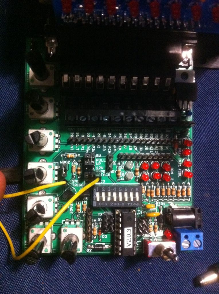
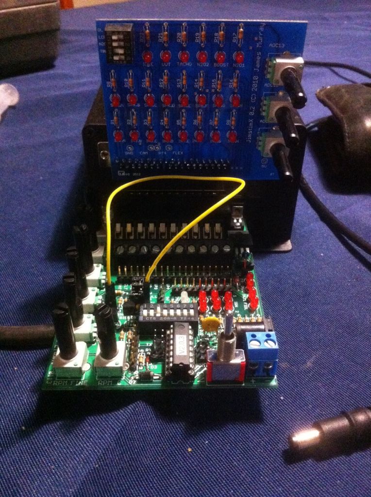
well ive gotten my jimstim and build it all up think ive gotten things set up correctly
|
||||||
|
8604 Posts Member #: 573 Formerly Axel Podland |
26th Oct, 2013 at 08:04:40am
Ignition outputs on the MS3X as follows
Saul Bellow - "A great deal of intelligence can be invested in ignorance when the need for illusion is deep."
|
||||||
 1767 Posts Member #: 9165 Previously josh4444 Australia, brisbane |
26th Oct, 2013 at 09:02:27am
i see you change what ms gives out when wiring up the coils to the cylinders
|
||||||
 (2)[/url] by [url=https://www.flickr.com/photos/150672766@N03/]Rod Sugden[/url], on Fli) 5988 Posts Member #: 2024 Formally Retired Rural Suffolk |
26th Oct, 2013 at 09:49:25am
The JimStim in it's basic form only shows (ie, the top 4 LEDs) what a very basic MS1/2 gives out because it only plugs into your MS1/2/3 box via the 37 way connector.
Schrödinger's cat - so which one am I ??? |
||||||
|
8604 Posts Member #: 573 Formerly Axel Podland |
26th Oct, 2013 at 10:16:44am
Those coils are expensive.
Saul Bellow - "A great deal of intelligence can be invested in ignorance when the need for illusion is deep."
|
||||||
 1767 Posts Member #: 9165 Previously josh4444 Australia, brisbane |
26th Oct, 2013 at 10:46:06pm
o well ive already got them. so long as they do what the need to im happy
|
||||||
 (2)[/url] by [url=https://www.flickr.com/photos/150672766@N03/]Rod Sugden[/url], on Fli) 5988 Posts Member #: 2024 Formally Retired Rural Suffolk |
27th Oct, 2013 at 07:53:39am
On 26th Oct, 2013 Turbo This.. said:
im not sure i under stand on the top 37 pin plug you have a-h outputs with leds for both spark and fuel i have dip switch 3 active or i dont get the fuel OK, I didn't think the MS3X board had its own LEDs.... I don't use MS3 so I could be wrong but I thought that's why they developed this to watch its outputs without jumpers down to the JimStim. 
Unless you bought one of them as well as the JimStim, I had assumed you would be set up something like this (random picture found on the internet) 
In which case what I would be doing is running jumper wires down from the top socket to the spare LEDs on the JimStim board. But if the MS3X board has its own LEDs or you also bought one of those additional display boards, ignore me 
On 26th Oct, 2013 Turbo This.. said:
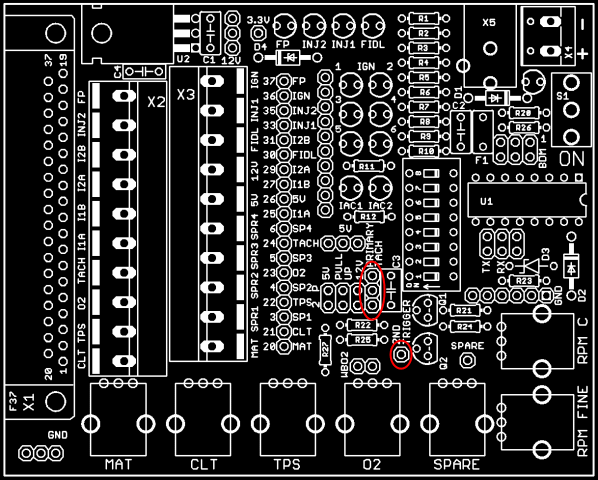
on the bottom 37 pin plug ive got the jumper from tach out put to 2nd trigger aswell as both jumpers for a 5v pull up those are running parrall with the main chip and the cam selection jumper is towards the pots the other jumper is the wide band one 3rd dip switch is on for the 36-1 aswell It depends how your MS3/MS3X is set up for the second (cam) input. If you are using the spare opto circuitry on the main board, you jumper the JimStim second trigger to whichever SPR pin has been used on the main connector but if you are using the 2nd VR circuit on the MS3X board, then you have to run a jumper wire up from the JimStim to the relevant input pin on the MS3X connector (pin 32 according to the diagrams) which is what you see in my random internet piccy. And the MS3 has to be configured through TunerStudio for whichever input you have chosen. Schrödinger's cat - so which one am I ??? |
||||||
 1767 Posts Member #: 9165 Previously josh4444 Australia, brisbane |
27th Oct, 2013 at 09:28:19am
ok ive got both boards so just a case of setting it up correctly
|
||||||
 (2)[/url] by [url=https://www.flickr.com/photos/150672766@N03/]Rod Sugden[/url], on Fli) 5988 Posts Member #: 2024 Formally Retired Rural Suffolk |
27th Oct, 2013 at 12:19:15pm
OK, I thought you had just bought the JimStim by itself.
Edited by Rod S on 27th Oct, 2013. Schrödinger's cat - so which one am I ??? |
||||||
 1767 Posts Member #: 9165 Previously josh4444 Australia, brisbane |
27th Oct, 2013 at 10:48:03pm
ok ive just read the set up page for the wheel again and i think ive allmost got it correct lol
|
||||||
 (2)[/url] by [url=https://www.flickr.com/photos/150672766@N03/]Rod Sugden[/url], on Fli) 5988 Posts Member #: 2024 Formally Retired Rural Suffolk |
28th Oct, 2013 at 06:50:16am
On 27th Oct, 2013 Turbo This.. said:
ill be using two hall type sensors one for crank and one for cam so that means ill need the square wave simulation right? Yes. So the jumper belongs on the left two of the three pins, not the right two like the drawing I included. Be aware that it is only the primary tach where you have the choice of square/VR, the secondary is square only which might help explain the next bit, On 27th Oct, 2013 Turbo This.. said:
then the leftover tach pin part of that same line of pins also right next to no 1 dip switch is hooked to the 2nd trigger as per pics above No - although the layout is a bit confusing, the only thing that block of nine pins does for the secondary tach is set 12 or 5 Volt pull-up. The secondary tach signal comes only as a square wave from the single pin and you have to jumper it to somewhere completey different and where it goes depends on how your MS3/MS3X is configured as I explained above. On 27th Oct, 2013 Turbo This.. said:
the part i think ive gotten wrong is do i need the primary or secondary pull up also 5v or 12v lol as you point out i have both p and s jumped for 5v... If they are both Hall switches the 5V (both) should be fine. On 27th Oct, 2013 Turbo This.. said:
do i need both p and s as im useing both wheel sims? Yes, if you are running (eventually) sequential injection and, most definately yes for COP. The secondary signal is how the code knows whether to fire No 1 or No 4 etc. What you need to know is how the MS is physically configured for the secondary tach signal, mainboard circuit or MS3X circuit. Did you build or configure it or did you buy it already built/configured ? Schrödinger's cat - so which one am I ??? |
||||||
 1767 Posts Member #: 9165 Previously josh4444 Australia, brisbane |
28th Oct, 2013 at 09:00:22am
yess both hall type sensors so dose that mean ive got it correct (the jumpers in the above pics)
|
||||||
 (2)[/url] by [url=https://www.flickr.com/photos/150672766@N03/]Rod Sugden[/url], on Fli) 5988 Posts Member #: 2024 Formally Retired Rural Suffolk |
28th Oct, 2013 at 09:33:13am
As you are using the V3.57 mainboard I assume you will be using the MS3X card for the cam input (configuring a V3.57 board for all the extras (like cam) is nowhere near as easy as a V3.0).
Schrödinger's cat - so which one am I ??? |
||||||
|
8604 Posts Member #: 573 Formerly Axel Podland |
28th Oct, 2013 at 10:19:33am
Don't forget that the recommended connection method for a crank hall sensor on MS3 is through the VR circuit. That's how mine is connected on my V3.0 board.
Saul Bellow - "A great deal of intelligence can be invested in ignorance when the need for illusion is deep."
|
||||||
 (2)[/url] by [url=https://www.flickr.com/photos/150672766@N03/]Rod Sugden[/url], on Fli) 5988 Posts Member #: 2024 Formally Retired Rural Suffolk |
28th Oct, 2013 at 10:49:26am
On 28th Oct, 2013 Paul S said:
How do you select the VR or hall/opto circuit on the V3.57 board? With conventional jumper plugs apparently.... and a little bit of SMD soldering but hopefully that will have been done by the supplier (I hate SMDs) Josh, you'd better check that resistor (R57) has been installed. http://www.msextra.com/doc/ms3/ignition.html#tachint357 (and click on the V3.57 at the top of the page if the link doesn't go straight there) Edited by Rod S on 28th Oct, 2013. Schrödinger's cat - so which one am I ??? |
||||||
|
8604 Posts Member #: 573 Formerly Axel Podland |
28th Oct, 2013 at 11:10:03am
Rod, you don't need the pull-up resistor in R57 if you are using a hall sensor with an internal pull-up. Saul Bellow - "A great deal of intelligence can be invested in ignorance when the need for illusion is deep."
|
||||||
 (2)[/url] by [url=https://www.flickr.com/photos/150672766@N03/]Rod Sugden[/url], on Fli) 5988 Posts Member #: 2024 Formally Retired Rural Suffolk |
28th Oct, 2013 at 11:18:24am
Paul, good point..... Schrödinger's cat - so which one am I ??? |
||||||
 1767 Posts Member #: 9165 Previously josh4444 Australia, brisbane |
29th Oct, 2013 at 06:19:55am
so at the the way ive got it set up its just useing the crank angle and not seeing the cam due to the cam beeing on the top 37 pin vs the wheel simulator makeing both signals on the lowwer 37 pin.. ill have a play and see if i can jump the 2nd tach signal up to the cam pin in the top plug migh need to solder a pin on as i dont rember any pins being put in the top bord..
|
||||||
 1767 Posts Member #: 9165 Previously josh4444 Australia, brisbane |
29th Oct, 2013 at 06:50:08am
right ive just soldered in the pin for cam input on the top bord and jumped the 2nd triger to the new pin and bam its fireing each coil at a time abcd abcd YAY! so when its wired i just hook it up as said by paul A > 1 B > 3 C > 4 D > 2 and away we go hopefully haha
|
||||||
| Home > Show Us Yours! > Josh's turbo 1098cc carburetion sucks lets try EFI | |||||||
|
|||||||
| Page: |


