Donations towards server fund so far this month.

 
£0.00 / £100.00 per month
Page:
Home > Show Us Yours! > Josh's turbo 1098cc carburetion sucks lets try EFI

Turbo This..

User Avatar

1767 Posts
Member #: 9165
Previously josh4444

Australia, brisbane

i need to sort me some more parts for the exhaust need T3 flanges as well as bits to make some sample chambers
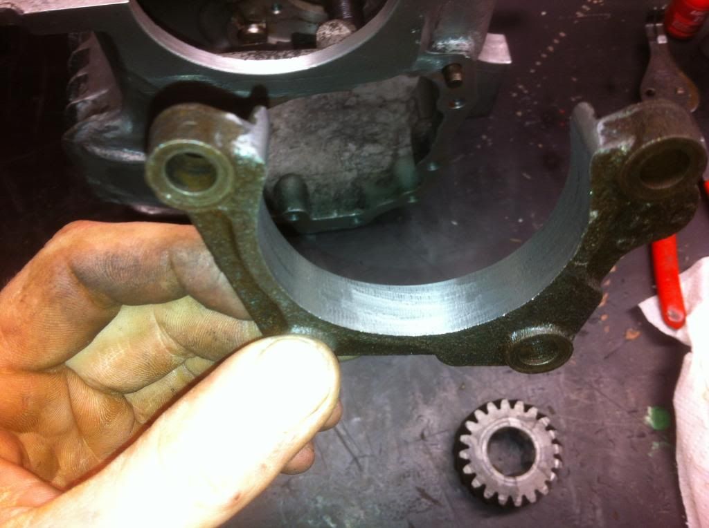
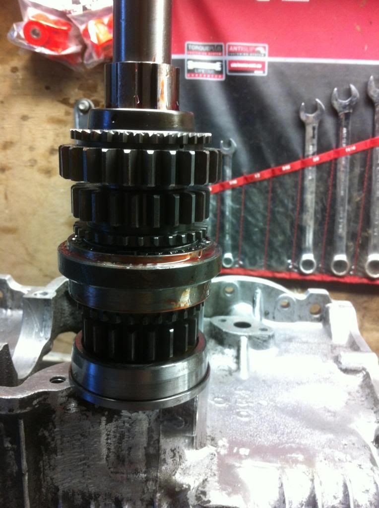
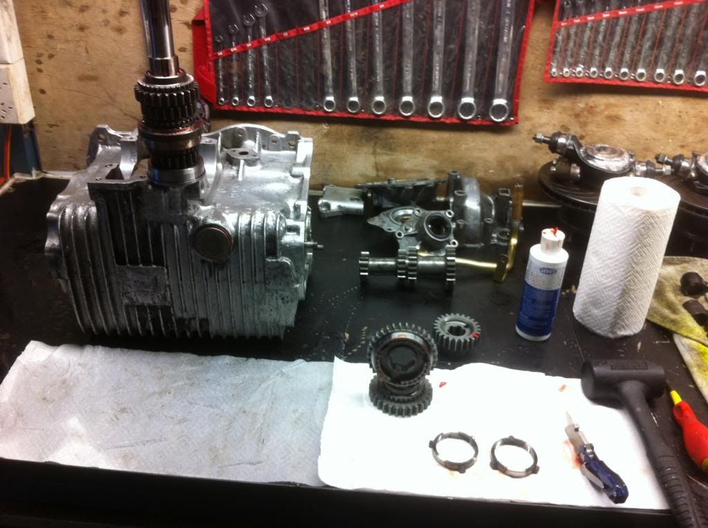
ive started cleaning and reassembling the box with the 2.95:1 diff need to die grind the retainer and drill a oil temp hole in the speed o housing


Turbo This..

User Avatar

1767 Posts
Member #: 9165
Previously josh4444

Australia, brisbane

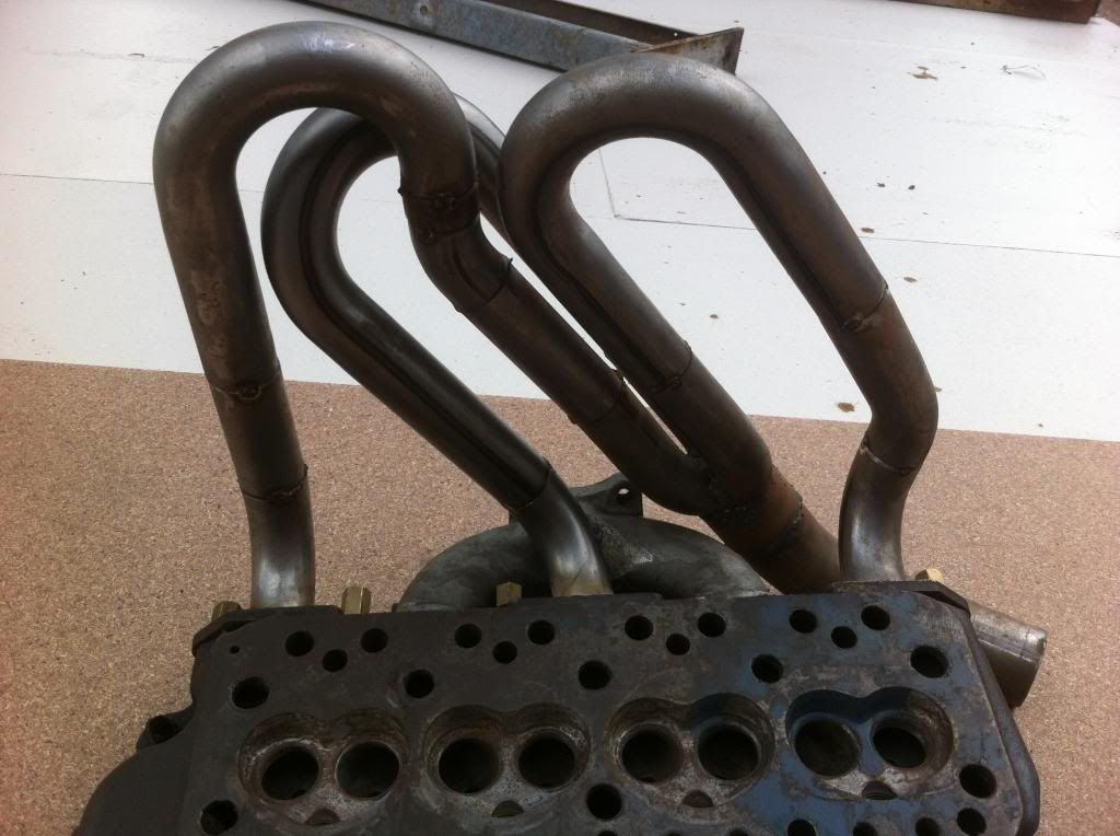
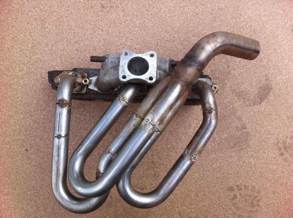
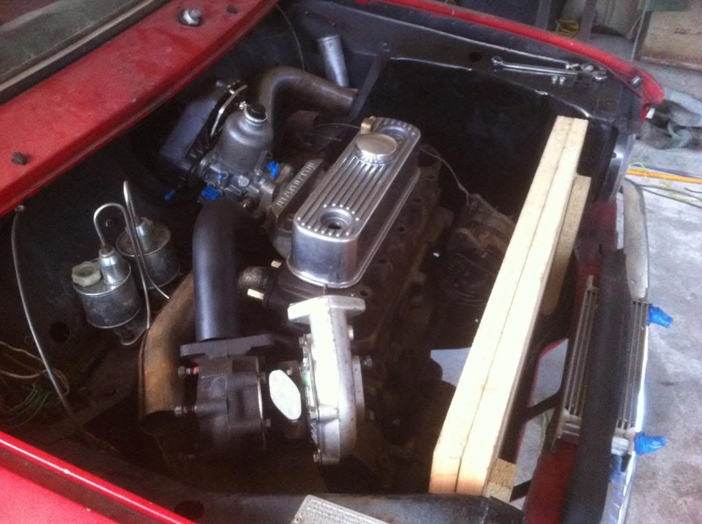
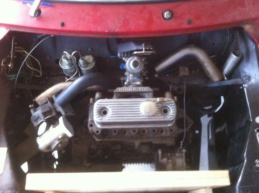
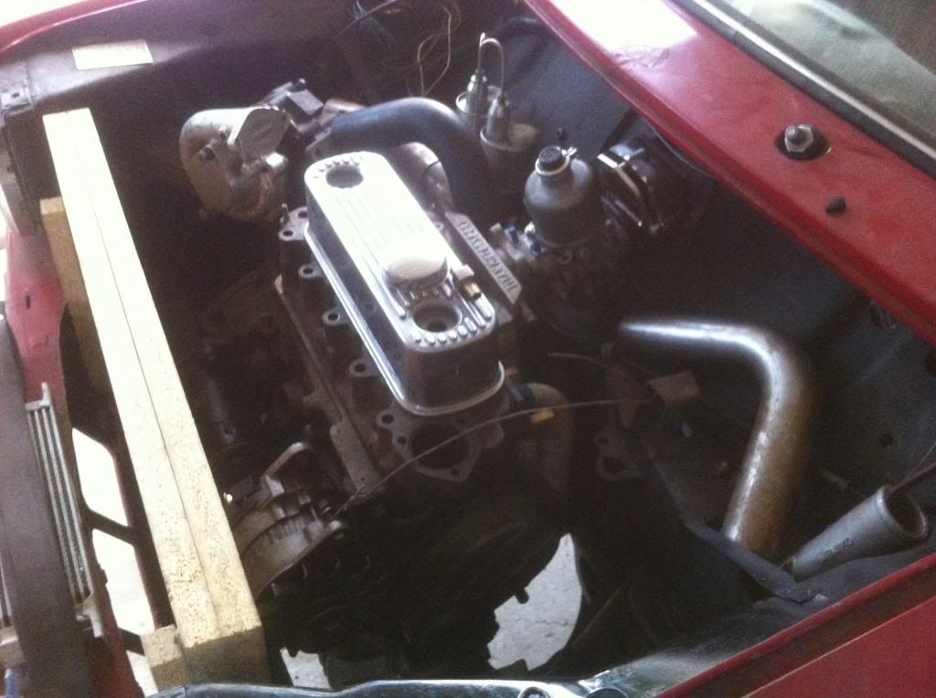
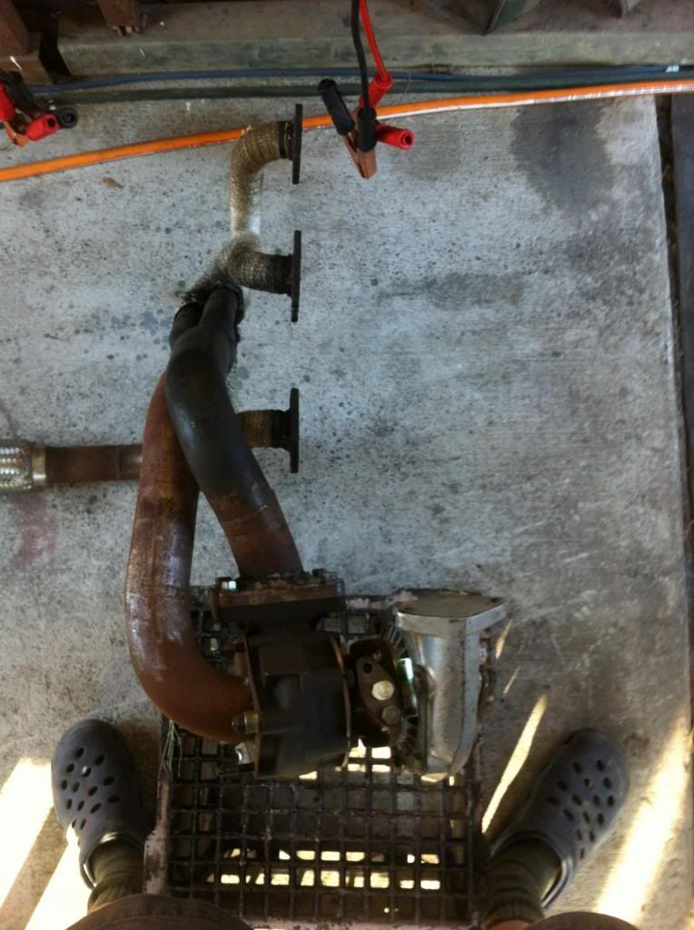
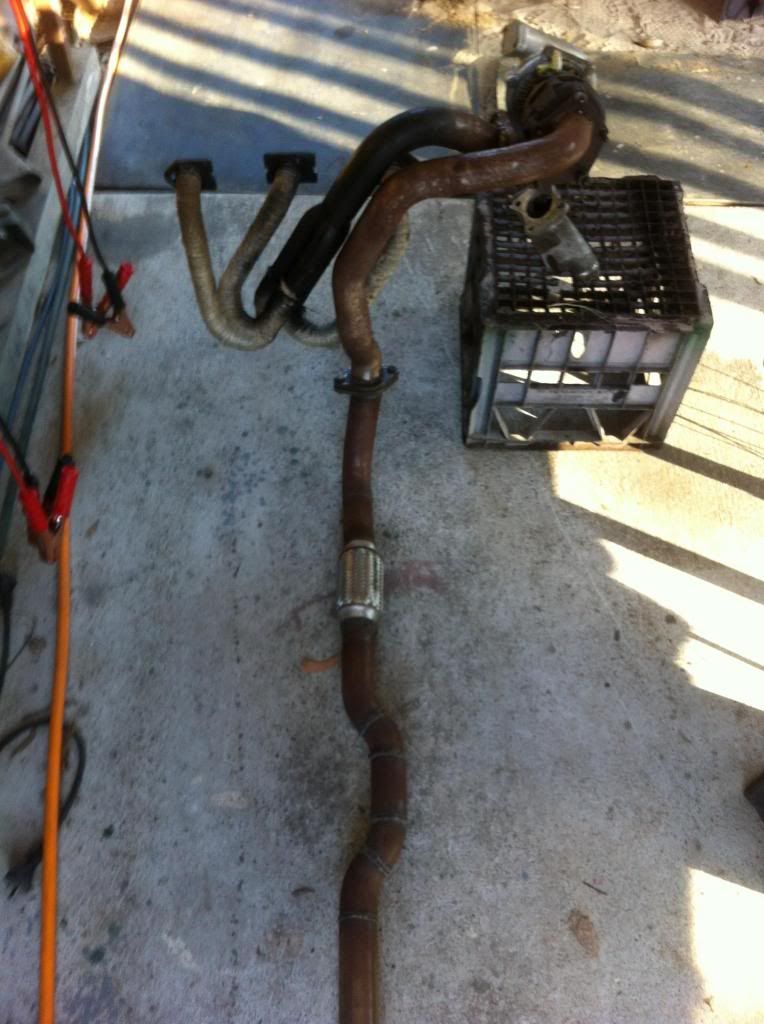
ok so i have doing the normal two steps forward 1 back i dont know how Manny times i cut welded re cut and re welded the dam manifold just to get this far n it still has no down pipe! lol at least its going forwards i guess..
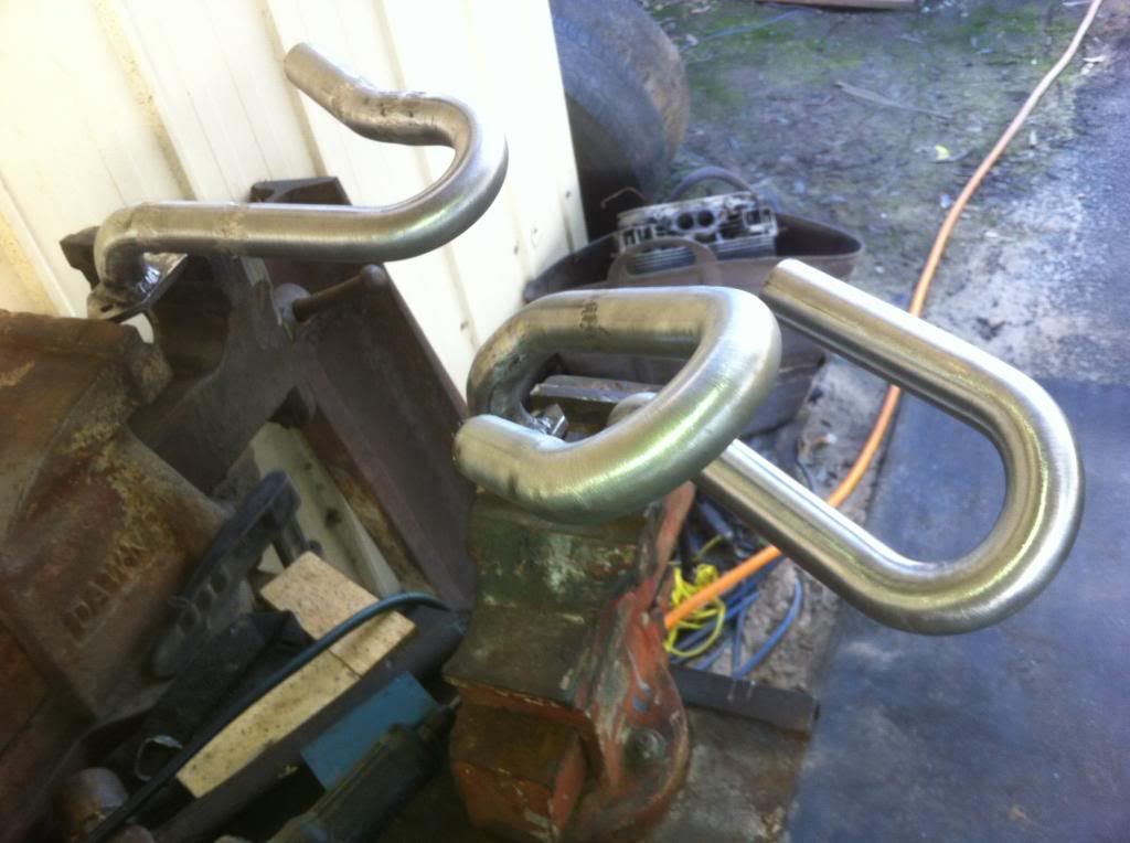
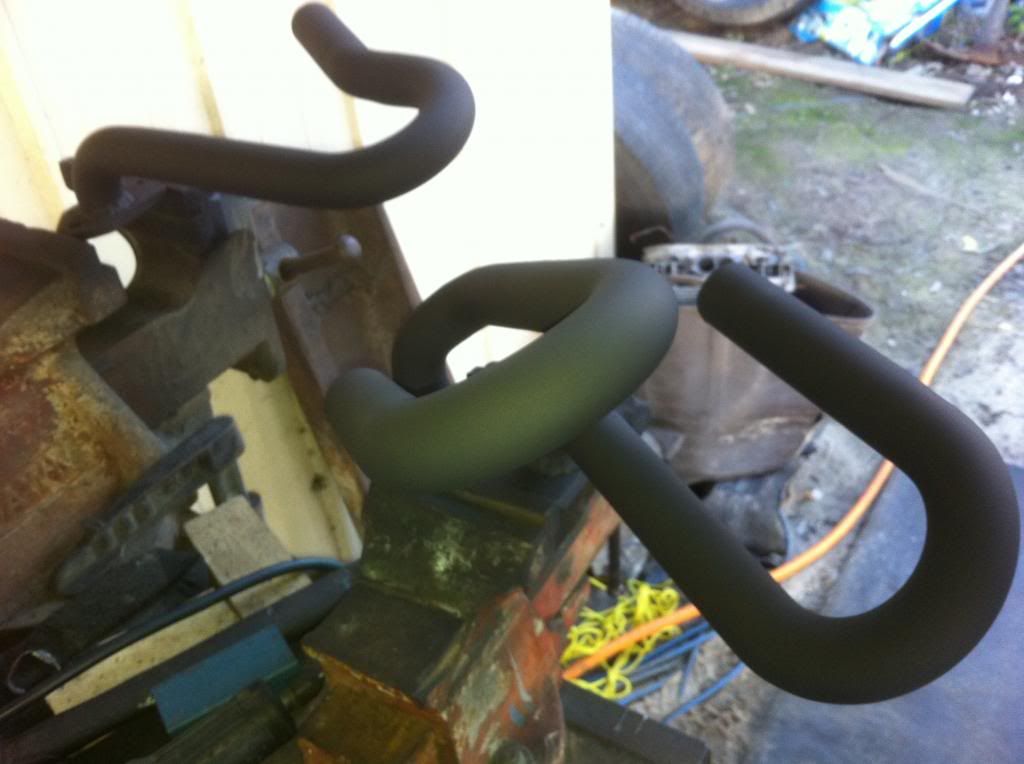
so picture are better than words most of the time..

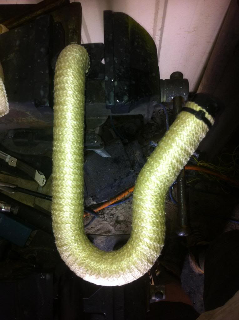
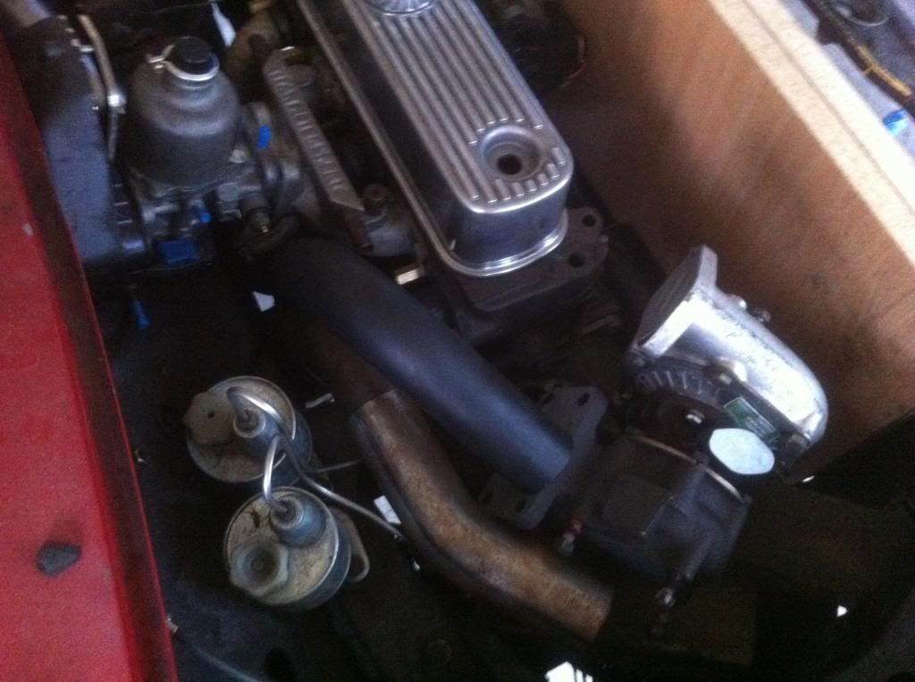
the manifold is painted with a diy product called vht flame prof i have done this because in i have read that if you wrap an exhaust it promotes rust so i painted it also vht is supost to be if done right a ceramic paint/coating so should help with keeping heat in also warped it and have a turbo blanket so with all that i hope that i can keep the exhaust gas hot and fast inside where it belongs


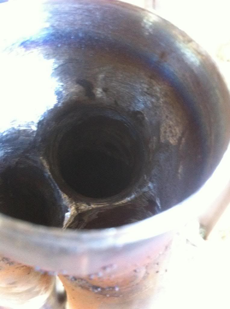
the inside was ground smoth at the places i could get to and the rest where hopefully welded 90% the wall thickness with the crappy gas less welder =/

i welded the three runners on after wrapping them to get as much wrapped as a single pipe ill then go back over the collector and remainder once finished at a stand still due to needing turbo flanges so moved on to putting a proper diff in


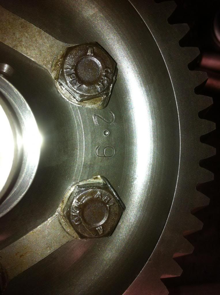
also re did the gear set as i was not happy that it felt stiff and hard to turn over by hand since re doing it its still the same anyone know how much if any resistance a brand new sccr box should have its useing new gen rover bulk rings, selectors, selector hubs, gear set and bearings at this point im putting it down to everything being new and tight?

im going to make a few heat shields i think


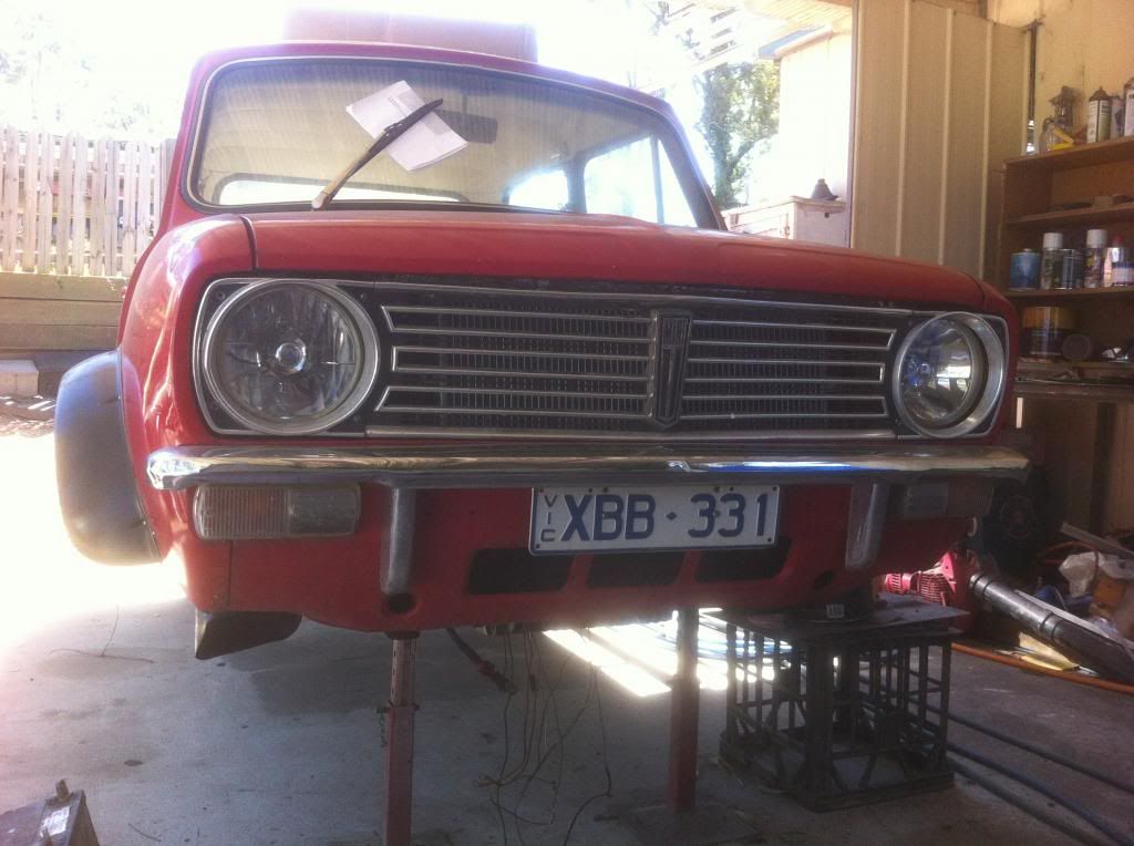
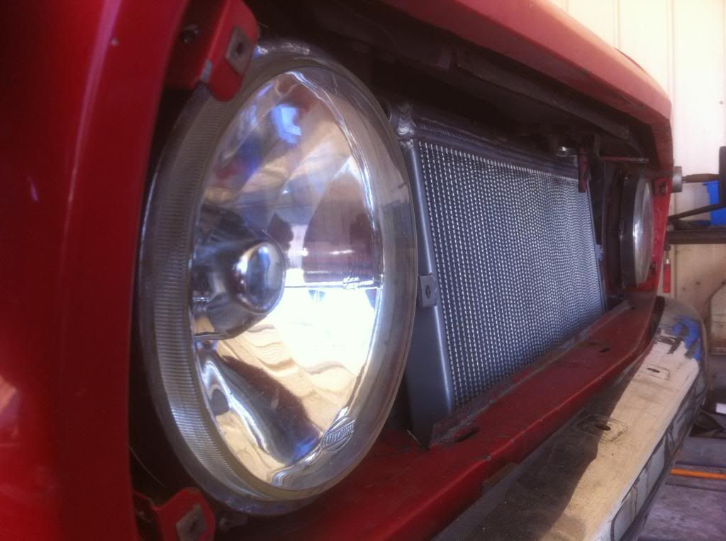
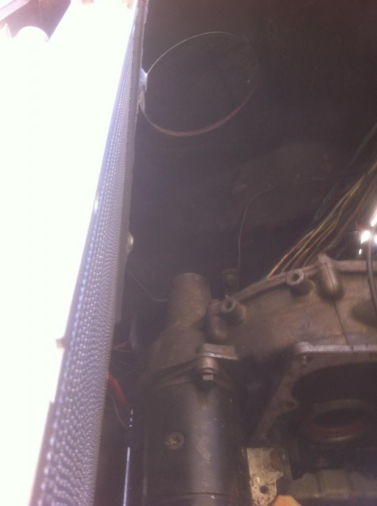
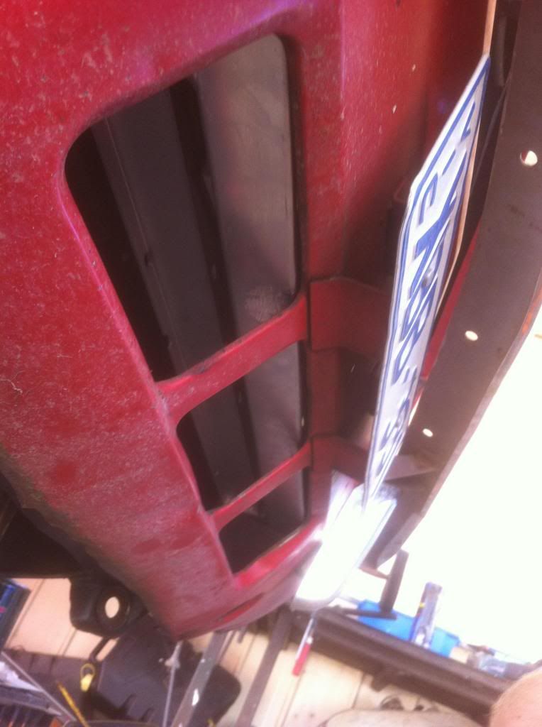
i have removed the std rad and filled the hole as i plan to fill the gaps and route the air flow in the grill throw the IC, rad, oil cooler then around the motor towards the turbo and hot parts then force it under the car into a low pressure zone im hopeing it works and things dont become stupidly hot i will be making a fair amount of ducting and sheet metal to route air flow if not ill cut the old rad hole back in and change some stuff lol

i have a bunch of goodies coming soon so i can move forth at this point im quite keen to get moving on this


Turbo This..

User Avatar

1767 Posts
Member #: 9165
Previously josh4444

Australia, brisbane

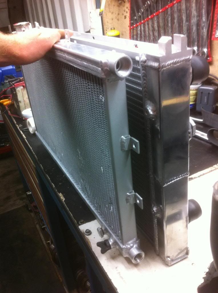
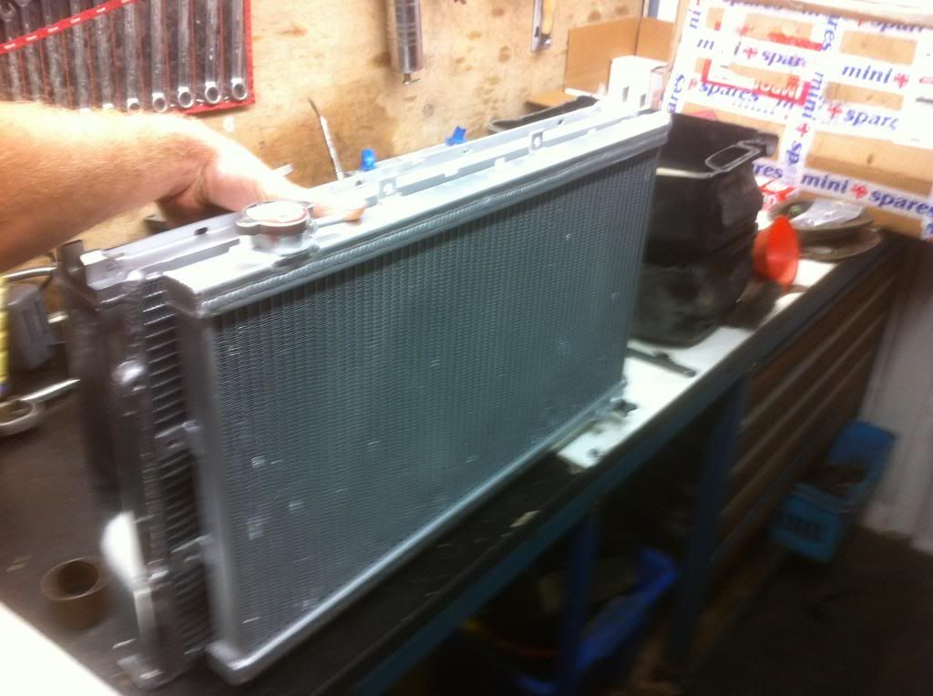
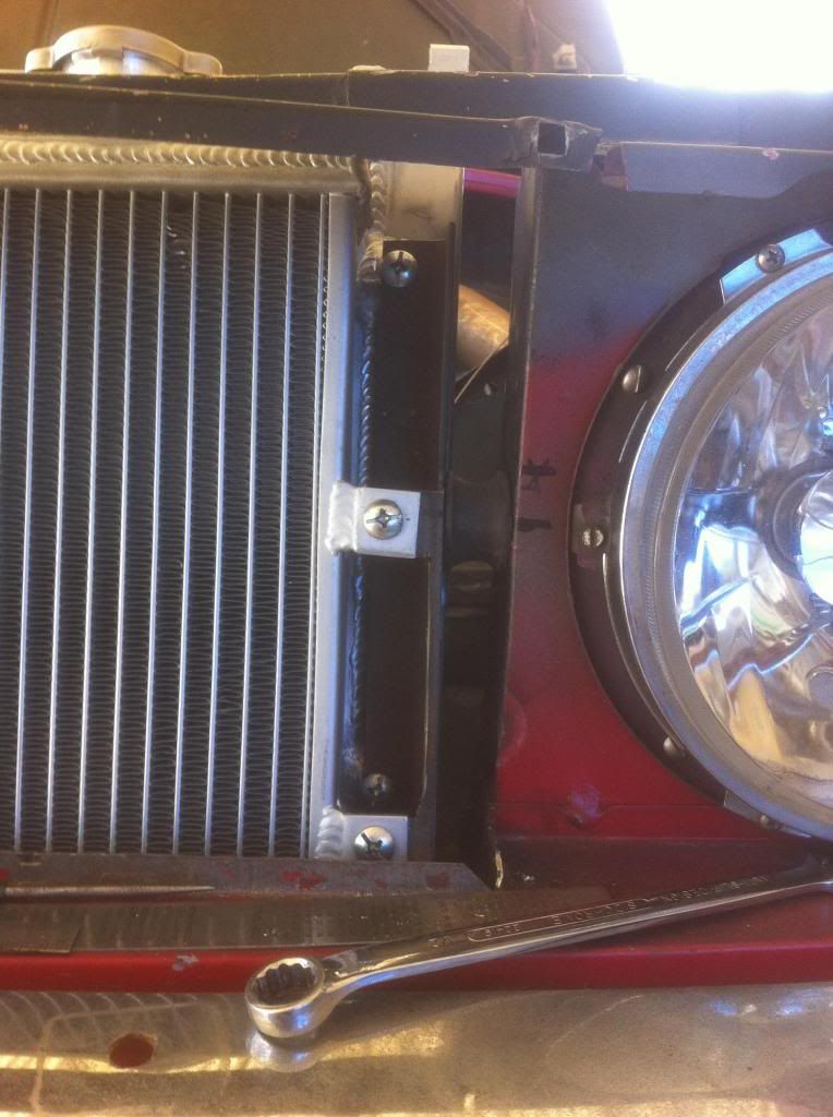
small up date with pics got my radiators the big one mounted at the back is for engine coolant and smaller one is for inter cooler coolant going to run liquid-air for the inter cooler
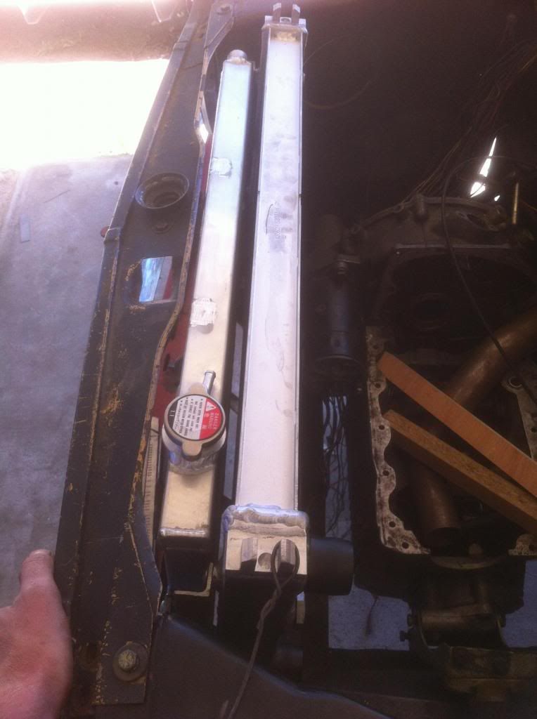
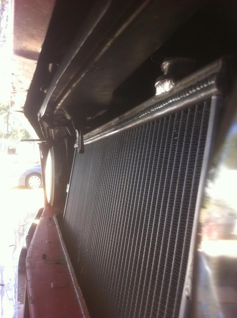
the rads will be mounted with a decant air gap to prevent heat soaking between them also will have twin electric fans controlled by two temp senders one for each so if ether inter cooler or rad get hot the fans come on well thats my cunning plan hope it woks like i think it will....

waiting for the shop to get a decant window where they can get a clean work bench to spread out on and do the work all at once
anyone want a 1098cc crank to cut up into cross sections i have 3 dead cranks... if i can give the one i had in my car a good whack and brake it in two ill make a trophy lol thats how close the shop recons it is to braking in two


edit forgot pics...


Edited by Turbo This.. on 22nd Aug, 2013.


pinkyandnobrain

User Avatar

720 Posts
Member #: 2588
Post Whore

Pretoria South Africa

Love the manifold ! What about having the dump pipe exit out the drivers side a-panel ?

"So wat we gonna do tonight Brain?"
"Same thing we do evernight Pinky!"
"Try to take over the world!"


Turbo This..

User Avatar

1767 Posts
Member #: 9165
Previously josh4444

Australia, brisbane

pink thanks im hoping to get good torque whilst working out how to arrange it all i thought id love to stick the hot turbo out the bonnet but that gives the game away im looking for a standard look i will be going down to 12" x 5" and possibly loosing the arches with a simple chrome strip


Turbo This..

User Avatar

1767 Posts
Member #: 9165
Previously josh4444

Australia, brisbane

so this morning has been productive mounted some stuff
brackets still needs some cleaning up and top mounts need making
im pleased with the fit


gr4h4m

User Avatar

4890 Posts
Member #: 1775
Post Whore

Chester

Nice

I run a supercharger and I don't care the TB is on the wrong side.
VEMS + 12 PSI + Liquid Intercooler = Small Bore FUN!


norm74

User Avatar

54 Posts
Member #: 2819
Advanced Member

south east, Melbourne, Victoria, Australia

stupid question is the rad going to be any good to drop temp chargers as its sits right behind the intercooler. it looks pretty close in the engine bay.
i know you have fans to go in, also when driving you get air flow, but it looks like the frontal area of the intercooler is way to big for its purpose, i thought when you run a water-to-air cooler you dont need them to be as big as and air-to-air one.

just my thoughts, im just asking thats all.

robert

everybody likes free stuff


apbellamy

User Avatar

16540 Posts
Member #: 4241
King Gaycharger, butt plug dealer, Sheldon Cooper and a BAC but generally a niceish fella if you dont mind a northerner

Rotherham, South Yorkshire

We ran an intercooler & radiator sandwich in the metro van with a single fan on the rad. Worked really well.

On 11th Feb, 2015 robert said:
i tried putting soap on it , and heating it to brown , then slathered my new lube on it

*hehe!*


robert

User Avatar

6745 Posts
Member #: 828
Post Whore

uranus

really nice exhaust manifold design .

Medusa + injection = too much torque for the dyno ..https://youtu.be/qg5o0_tJxYM


Turbo This..

User Avatar

1767 Posts
Member #: 9165
Previously josh4444

Australia, brisbane

thanks guys

all goes well my wacky plans work out there are more odd/different? things im going to try out stay tuned

norm the IC rad is in front as you want that as low as possible using water/meth injection you can get below ambient temp too
i think heat soak between rads wont be a problem sitting at the lights/trafic due to the 25mm gap between them also the tanks also are 90 degrease out keeping the mojorty of heat away from each other if that makes sense?

its funny how your ideas change as you implement them and sometimes they work out better than intended
i was not planing on tilting the rads backwards but having done that i can use the std bonnet latches and i have more space for the fan shroud giving a more equalized flow also i can get to the drain and temp sender plugs on the ic now with out removing it SCORE

going to re install the heater tomorrow its ether smoking hot or freezing cold only took it out to pillage the core for additional engine cooling..

also might tackle the job ive been putting off for ages.. i need to find the speedo ratio for the correct reading ive had a look see on guess works and i cant find the numbers they talk about that tell you so ill have to count the gears and stuff and do the sums buga!

dose anyone know how to set up a digital speedo throw MS? id like to see my 0-100-0 time and other speed time related things like gear changes getting on and off the gas and brakes to better my skills lol

time to hammer the search function


Turbo This..

User Avatar

1767 Posts
Member #: 9165
Previously josh4444

Australia, brisbane

a small update
i have not been successful with the speed o ratios nothing looks the same as the gussworks page so i give up on that for now ill come back to it lol

the shop has got a start on my engine so soon ill have that fun bit to do after ive sorted my compression ratio out

norm i think i have miss read your post i have gone for an over the top rad combo as i think its better than not haveing enough
ill also find a way to get air to the lower section of rads that is mostly shrouded by the body
the engine rad should see air that is only a few degrees above the ambient air im hoping as if it get much hotter than the ambient air that means that the ic is to hot to start with and not going to do its job im looking for really low intake charge temps so i can have more boost to make more power


Turbo This..

User Avatar

1767 Posts
Member #: 9165
Previously josh4444

Australia, brisbane

slow progress.. but progress none the less..
wating on parts atm so doing small things like turbo oil drain, breathers, oil cooler mounts, finding a spot of the huge remote oil filter, mounting the rod change short throw shifter in a remote shifter body, running new fuel lines the things ive been putting off really
engenieingreing shop hasnt started yet as its a cash/on the side job and its a "fit it in when you can" type of thing anyway said they should get a start on it this week comeing...
i am sort of loseing motivation at the moment due to not knowing if im welcome where im liveing anymore so sort of reluctant to spend time/cash on the project vs find some where else to live atm never less pushing forward..


Turbo This..

User Avatar

1767 Posts
Member #: 9165
Previously josh4444

Australia, brisbane

i have opened up my ms3x stuff tonight to have a look see at soldering up the plugs and looms relating to what ill use both straight up and what may get used later id like to solder up the full plugs and tuck the extra wires away so i dont need to mess about later when doing efi/adding to the car

so id like to check with you guys that have been there and done that... before i solder it up and make mistakes..

if my thinking is correct? ill need both the db 37 plugs both top and bottom
as the cam input goes to the upper plug and crank input goes to the lower plug
my spark (4 x cnp) and injectors when i get to it both upper plug
air temp, coolant temp, throttle position (will i need this to use the hif44?), fuel pump out put, on lower plug
it looks like the wide bands inputs are one to each corrector?

the link below is what im looking at
it seems i only have one wiring bundle the upper plug one is there a lower one or do you just make it up?

http://msextra.com/doc/ms3/hardware.html

i have 2x aem kits that arrived today as well
did some scrap yard digging and found me one of the nippondenso alternators = D payed 20 bucks for it with a v pully to go on it as well wait and see if it can deliver the goods =/
waiting on the cooling fans to come then ill fold up the shroud and wire up those


Paul S

User Avatar

8604 Posts
Member #: 573
Formerly Axel

Podland


On 20th Sep, 2013 Turbo This.. said:

if my thinking is correct? ill need both the db 37 plugs both top and bottom
as the cam input goes to the upper plug and crank input goes to the lower plug
my spark (4 x cnp) and injectors when i get to it both upper plug
air temp, coolant temp, throttle position (will i need this to use the hif44?), fuel pump out put, on lower plug
it looks like the wide bands inputs are one to each corrector?


I've just wired one up so this is still fresh in my mind.

That all looks correct. You will need a TPS for acceleration enrichment.

I got an extra MS3X plug (what you call upper plug) and wires from DIY Autotune.

Saul Bellow - "A great deal of intelligence can be invested in ignorance when the need for illusion is deep."
Stephen Hawking - "The greatest enemy of knowledge is not ignorance, it is the illusion of knowledge."


Turbo This..

User Avatar

1767 Posts
Member #: 9165
Previously josh4444

Australia, brisbane

thanks paul no doubt i will have Manny more questions as i work throw the build/tune

also whats the smaller 15 pin connector for?

the square usb and 9 pin are for tuning right?

what brand/type of tps should i use on the hif =/?

i dont supose you know witch pin is what on the iat and clt?
http://www.diyautotune.com/catalog/gm-open...ctor-p-116.html
http://www.diyautotune.com/catalog/gm-clos...ctor-p-115.html

do you recommend getting the simulator thing to play/set up with on the bench?


Turbo This..

User Avatar

1767 Posts
Member #: 9165
Previously josh4444

Australia, brisbane

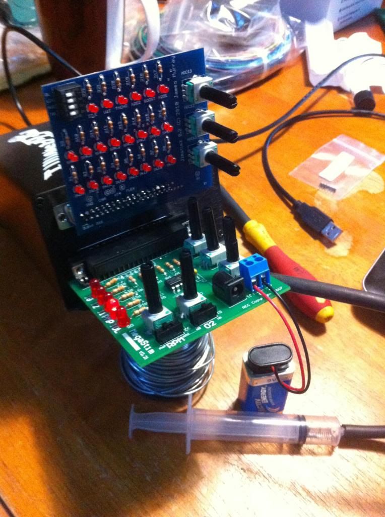
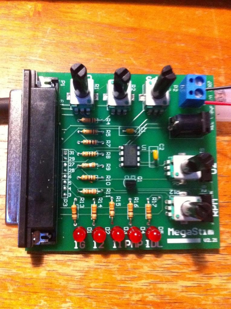
well ive built up the megastim and jimstinx boards for the ms3x and it seem i cant get the rpm pot to work properly?
all the other stuff seems to work coolant, intake air temp, tps, wide band but the rpm whont give me input ive swaped out the pot and switch for the o2 ones with no change so guess i can rule out those components so must be something else ive scrwed up?
had a good look over for crappy soder joints but cant find anything?
seams a basic pcb so perhaps its in the programming?
not sure its late and my eyes hurt so im done tonight start over fresh tomoz

shop has made a start done first crank grind (its off getting heat treated atm)
block needed a re jig as it had run out and egg shaped =S

just need to install the foam filler strips on my rad/fan shroud
waiting on my pipe bender to finish the fuel lines

basically not much going on kinder dragging my balls a bit as its been hot out lately.. well thats my excuse!


Rod S

User Avatar

5988 Posts
Member #: 2024
Formally Retired

Rural Suffolk

Not quite sure what you mean by "magastim and jimstimx" boards.

The usual wording of "megastim" implies the original simulator which simply doesn't do toothed wheels.

Post a photo of it so I can be sure.

For dealing with any toothed wheel setup you need a "JimStim".... NOT to be confused with a jimstimX which is purely for the MS3 outputs and additional inputs and only works (I think) with the JimStim.

If you are using a basic "Stim", yes, all other inputs work, but not the crank/cam (ie RPM) signals.

Schrödinger's cat - so which one am I ???


Paul S

User Avatar

8604 Posts
Member #: 573
Formerly Axel

Podland

The latest Megastim should give a rpm signal.

Have you adjusted the VR pots:

http://www.msextra.com/doc/general/tachin-v30.html

Saul Bellow - "A great deal of intelligence can be invested in ignorance when the need for illusion is deep."
Stephen Hawking - "The greatest enemy of knowledge is not ignorance, it is the illusion of knowledge."


Turbo This..

User Avatar

1767 Posts
Member #: 9165
Previously josh4444

Australia, brisbane

ok so i have the two boards first one is megastim v2.21 and jimstimx 0.2

also have the ms3x v3.57 (the pre assembled computer built one) haven't opened or changed anything inside it i dont need to do i?

i have made a new project in tuner studio and that seems to be ok haven't changed any settings from what they start as tho
i did solder up the spare holes in the Bord as i thought they might join the top side to the bottom of the Bord circuits thought it couldent do any harm as surely if you put something in there and soder it up its going to join up anyways? can easly de soder it in need be..
have already de sodered and re sodered a good amount of the bord trying to find what ive done lol


Turbo This..

User Avatar

1767 Posts
Member #: 9165
Previously josh4444

Australia, brisbane

well ive just been playing with this a bit and its become apparent i need the wheel sim like you guys have said tried to sim 4 separate coils (CNP) like ill be using got a cam/crank input error when cycling power lol

bugga now i gotta wait for it in the post gah!


Rammie2000

User Avatar

1750 Posts
Member #: 10190
Post Whore

belgium

Your getting there. Very nice setup always loved it this way.

you can do anything if you set your mind to it...
i rather blow it up winning than keep it together losing.

finish date set for project 1... march 2018


Rod S

User Avatar

5988 Posts
Member #: 2024
Formally Retired

Rural Suffolk

Yes, the photo shows it's just the latest version of the basic "Stim". The chip in the middle is just a 555 timer so the only RPM output it emulates is a plain symetric square wave of conventional ignition setups (ie, points) and not the missing tooth profile you need, and certainly no phase (cam trigger) output which you need if you're doing sequential.
Allegedly they can make a "speed" signal sometimes if wound right up but no synch because no missing tooth which the MS requires to synch with how you'll have yours set up.

When your JimStim arrives, make sure you set it up right, best read is here http://jbperf.com/JimStim/index.html not just for getting the 36:1 wheel configuration set but also for where to put the extra jumper to provide the cam output (again only for sequential).


EDIT - also, get yourself a decent 12V power supply, that little 9V battery will be dead in no time and you'll very quickly pay more for batteries than the cost of a small power supply *wink*

Edited by Rod S on 9th Oct, 2013.

Schrödinger's cat - so which one am I ???


Turbo This..

User Avatar

1767 Posts
Member #: 9165
Previously josh4444

Australia, brisbane

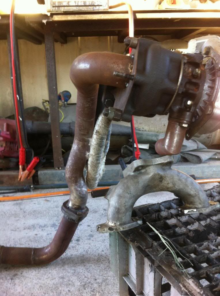
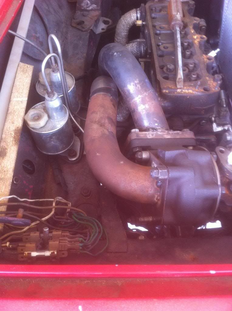
just some more pics of my bogy work haha

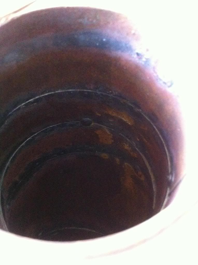
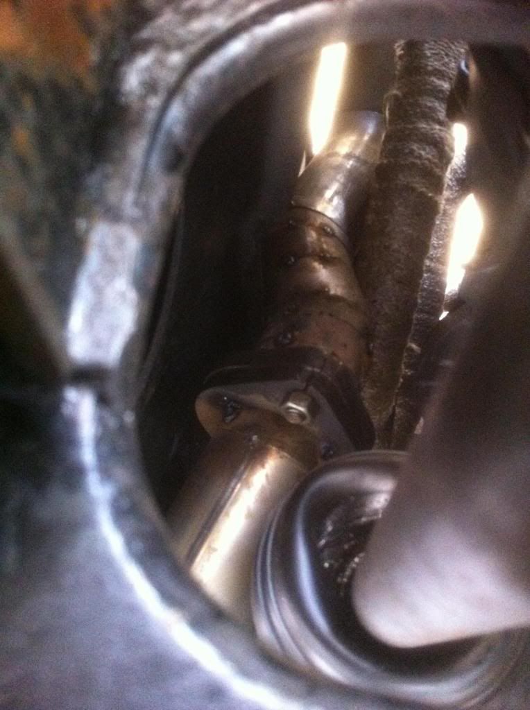
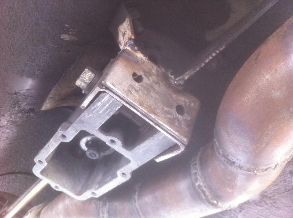
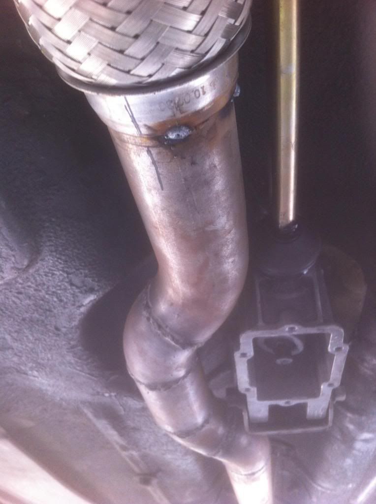
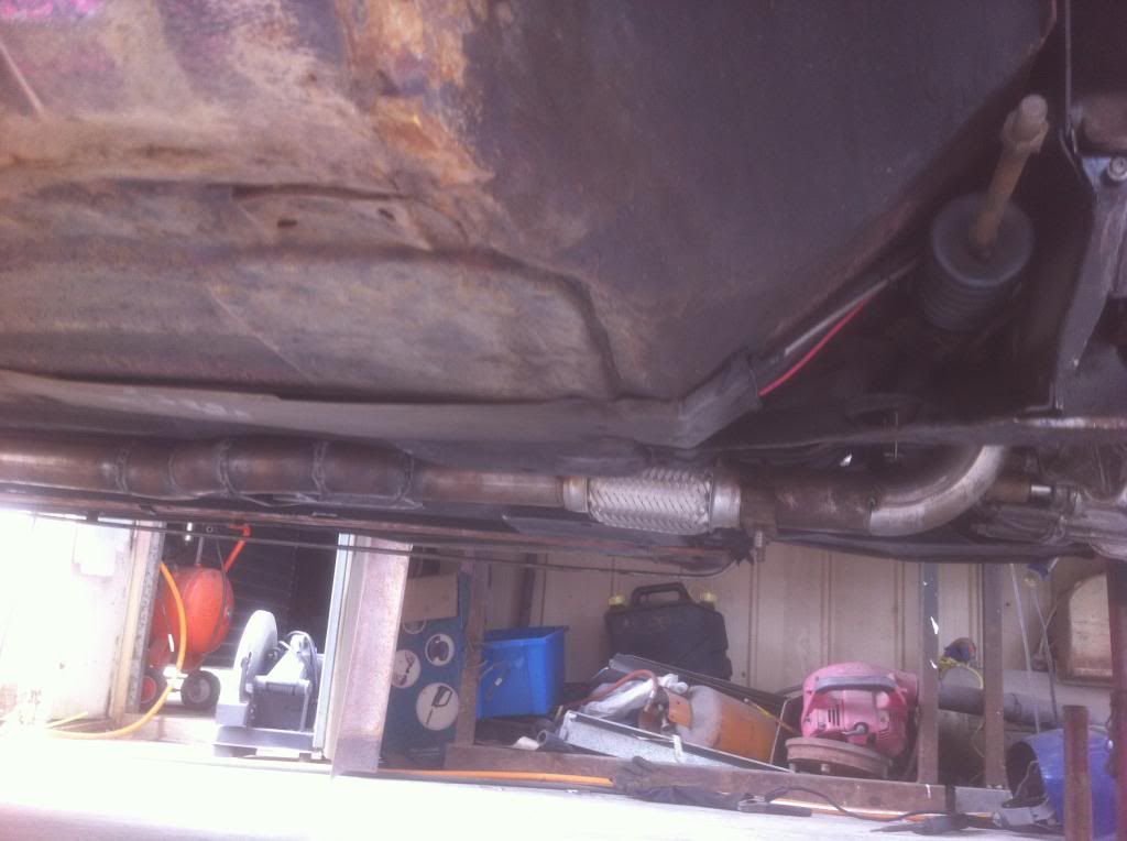
i hope it holds up to the heat wont melt anything surrounding it! will be wrapped like the headers and have some tin shields in a few spots to help out a bit i hope?

managed a nice turbo drain that doubles as a breather for the drop gear side including rocker cover other side will prob be from the timeing chain and lifter chest
bit of a struggle to get the down pipe through but managed it

need a 2"-2.5"reducer to fit the flange


i made the exhaust feed pipe shape and insert into the turbo as to maintain a nice smooth flow

adapted the shifter from remote to rod and wiggled the exhaust past it


kinder ticked up out of sight a bit


fitted the bits n thing onto my fan shroud inter cooler rad combo this arvo although i only managed to fit one 12" fan hopefully its up to the job
there is not as much air mass moving throw them as id hoped for but the shroud is doing its job! nice equal flow all the way into corners so thats good no dead spots
clearance is kinder tight tho!
mounted the oil filter and cooler just need the hoses made up and thermostat to finish that up filter is in a nice easy place to service it
fuel lines and reg half done need the bender
plenum chamber just needs welding once charge cooler arrives to get a straight shot between them
i still need to find a fuel pump that will be capable of doing of efi at a later stage and up to 22psi boost
working on the exhaust hangers and turbo supports at the moment
working on the coil near plug mounting next i think


Turbo This..

User Avatar

1767 Posts
Member #: 9165
Previously josh4444

Australia, brisbane

thanks paul

ahh ok my stuff up lol anyone want to buy a freshly build stim bord? haha

will get me a power supply do you know if its + inside the end or - if you know what i mean? lol err if you look at the male plug end the inner contact pin/sleeve bit + or - lol i thing it has a pic on the transformer normally? last thing i want to do is connect reverse polarity and blow it up


Home > Show Us Yours! > Josh's turbo 1098cc carburetion sucks lets try EFI
Users viewing this thread: none. (+ 1 Guests) <- Prev   Next ->
To post messages you must be logged in!
Username: Password:
Page: