| Page: |
| Home > Show Us Yours! > K1100 16V Turbo build...now transmission build. | |||||||
 112 Posts Member #: 10125 Advanced Member Zoetermeer, The Netherlands |
4th Oct, 2012 at 10:21:34pm
On 4th Oct, 2012 matty said:
Yeah I basically figured with the gears being submerged in oil, and with the oil spraying off the crank, that should be enough to lubricate it. If needs be, some oil squirters could always be used. I would think the same about lubrication, which might only be more an issue for the output shaft, due to its higher position. The input shaft is literally submerged in oil.:) I have checked some pics of the seqeuntial MV gearbox of the 306 MAXI I'm doing. All non splined gears are on the secundary shaft and guess what: it is hollow and cross drilled for the needle bearings! The hollow shaft is fed with oil along the cover. In there is a kind of gutter, catching oil which is brought in by a plastic gutter from the gearcase. Honestly speaking in the mini gear setup I can't think out an easy way to feed the output shaft with oil when it would be hollow. Here you see the secondary shaft which I replaced to have a different final drive ratio. You see the cross drilled holes at each place where a (split cage) needle bearing is located later on. See the old one having traces of the needle roller bearings... 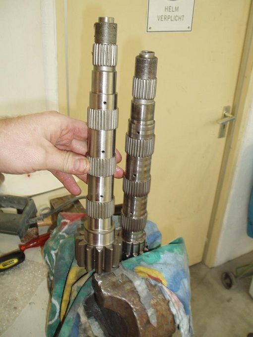
Here is the cover with gutter. The hollow end of the secondary shaft pops in the hole of the gutter (just left from the nut). 
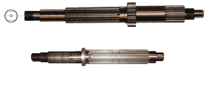
Just for fun an overview of the box internals: 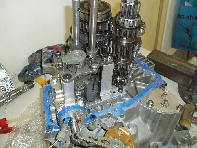
|
||||||
|
974 Posts Member #: 3228 Post Whore North of the Netherlands |
5th Oct, 2012 at 01:03:12pm
Hallo Bart,
Dazed and Confused.... |
||||||
 8297 Posts Member #: 408 Turbo Love Palace Fool Aylesbury |
5th Oct, 2012 at 02:31:14pm
Bart - im guessing those aren't pressure fead? The best thing to do is to fill the gearbox up with 3L of oil to see where the level sits (allowing 0.5L of oil to be elsewhere in the engine).
https://www.facebook.com/pages/Fusion-Fabri..._homepage_panel
|
||||||
 112 Posts Member #: 10125 Advanced Member Zoetermeer, The Netherlands |
5th Oct, 2012 at 05:42:38pm
Matty
|
||||||
|
974 Posts Member #: 3228 Post Whore North of the Netherlands |
6th Oct, 2012 at 11:36:27am
On 5th Oct, 2012 matty said:
Han - the main issue with that is that the geabox bearing sits exactly where the crankcase meets the gearbox case. So you would have to weld both the sections together first...nothings simple! lol Hmm, that doesn't make thing easier... And true, warpage is an issue, just found that sometimes using original parts make life easier. Having said that; in the hobby I haven't taken up a challange of this magnitude.. I really do like the way you both have taken up this challenge. I am an engineer from proffesion maybe that explains...... 
Good luck to both of you! Dazed and Confused.... |
||||||
 112 Posts Member #: 10125 Advanced Member Zoetermeer, The Netherlands |
8th Oct, 2012 at 10:01:23pm
On 10th Jun, 2012 matty said:
Ive just offered up my new bearing, and it looks like it should do the job nicely. It was the strongest bearing I could find that fitted in the space available...fingers crossed it holds up!  Matt, Nice needle roller bearing you have. For sure the space is not roomy where it has to come. But I wonder one thing now: Somewhere this shaft needs to be axially supported, though? Originally it was axially supported by the ball bearing on this location. This neelde bearing can't take axial forces. cheers, Bart |
||||||
 520 Posts Member #: 189 Post Whore Norway |
29th Oct, 2012 at 07:50:33am
On 10th Aug, 2011 matty said:
Here's a couple of pics of the whole setup. Apart from the ones on here, I don't think ive got any more of the turbo setup to be honest. 

This is before I had the flip front.  Hi mate. Do you have any pics of the ic with the front end on?? Trying to decide where to put my cossy ic and radiator :) www.shag.no |
||||||
|
337 Posts Member #: 399 Senior Member Austria |
6th Nov, 2012 at 06:56:35am
one month is gone since the latest entry. any successful advancements, matty? |
||||||
 8297 Posts Member #: 408 Turbo Love Palace Fool Aylesbury |
6th Nov, 2012 at 10:09:36pm
Vegar - I'll try and dig a picture out, im sure ive got one somewhere.
https://www.facebook.com/pages/Fusion-Fabri..._homepage_panel
|
||||||
 112 Posts Member #: 10125 Advanced Member Zoetermeer, The Netherlands |
7th Nov, 2012 at 03:24:33pm
Waiting never feels as a pleasure Matt, for sure.
|
||||||
 8297 Posts Member #: 408 Turbo Love Palace Fool Aylesbury |
7th Nov, 2012 at 07:49:46pm
Bart, from what I remember it was EN24, don't quote me on that though.
Edited by matty on 7th Nov, 2012. https://www.facebook.com/pages/Fusion-Fabri..._homepage_panel
|
||||||
 112 Posts Member #: 10125 Advanced Member Zoetermeer, The Netherlands |
7th Nov, 2012 at 10:29:32pm
|
||||||
 8297 Posts Member #: 408 Turbo Love Palace Fool Aylesbury |
8th Nov, 2012 at 10:00:06pm
My photo bucket seems to have changed to the 'new format' which seems to be geared towards FB and twatter.
https://www.facebook.com/pages/Fusion-Fabri..._homepage_panel
|
||||||
 112 Posts Member #: 10125 Advanced Member Zoetermeer, The Netherlands |
8th Nov, 2012 at 10:32:57pm
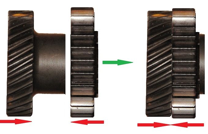
Trimming: one couple of gears of a Honda gearbox will be used for the connection from the mini input shaft to the honda primary shaft. I look for a couple which is close to 1:1, but I think it will be the 6th gear of the Blackbird box to be used. The gear with the bearing in it will be trimmed to fit the mini gears boss on the input shaft. So that means enlarging the hole and skim the dogs off. Below you see the merge of gears. Don't bother the helical one, as it just emphasizes the matter this is the transition point from mini to honda gear system.
|
||||||
 8297 Posts Member #: 408 Turbo Love Palace Fool Aylesbury |
9th Nov, 2012 at 08:45:43pm
Im splining my reverse gear, like you say above. Then im going to bore out another 1st/reverse gear and run it on the needle rollers that the original mini layshaft uses. Im guessing the mystery box is running the idler gear for reverse in constant mesh with the primary shaft.
https://www.facebook.com/pages/Fusion-Fabri..._homepage_panel
|
||||||
 112 Posts Member #: 10125 Advanced Member Zoetermeer, The Netherlands |
9th Nov, 2012 at 09:07:03pm
some processes, like splining, I am dependant to favours of friends or family. If not necessary, then I will not play that joker.
|
||||||
|
432 Posts Member #: 2726 Senior Member wakefield |
9th Nov, 2012 at 09:56:50pm
Amazing work mate, just reading it boggles my mind. :) |
||||||
 8297 Posts Member #: 408 Turbo Love Palace Fool Aylesbury |
9th Nov, 2012 at 10:09:07pm
Hmm ive just had a measure of the gears and that could work out well doing it your way....
https://www.facebook.com/pages/Fusion-Fabri..._homepage_panel
|
||||||
 140 Posts Member #: 10115 Advanced Member Sydney, Australia |
14th Nov, 2012 at 12:46:35am
Wow matty! This would have to be one of the best threads i've read. The best mini thread.
|
||||||
|
1909 Posts Member #: 9764 Post Whore Northamptonshire. |
14th Nov, 2012 at 11:33:46am
Matt quick question been puzzling me for few years now.
|
||||||
 12307 Posts Member #: 565 Carlos Fandango Burnham-on-Crouch, Essex |
14th Nov, 2012 at 11:43:08am
it is good practice to use a cover, but tbh I have never heard of a cam belt issue due to debris, and have seen a lot of cars wth no covers,
On 28th Aug, 2011 Kean said:
At the risk of being sigged... Joe, do you have a photo of your tool? http://www.turbominis.co.uk/forums/index.p...9064&lastpost=1 https://joe1977.imgbb.com/ |
||||||
 520 Posts Member #: 189 Post Whore Norway |
14th Nov, 2012 at 12:06:34pm
Try to visit the gravel traps outside the race tracks www.shag.no |
||||||
 12307 Posts Member #: 565 Carlos Fandango Burnham-on-Crouch, Essex |
14th Nov, 2012 at 12:13:18pm
that sounds like a good test! On 28th Aug, 2011 Kean said:
At the risk of being sigged... Joe, do you have a photo of your tool? http://www.turbominis.co.uk/forums/index.p...9064&lastpost=1 https://joe1977.imgbb.com/ |
||||||
|
1909 Posts Member #: 9764 Post Whore Northamptonshire. |
14th Nov, 2012 at 03:07:52pm
On 14th Nov, 2012 Joe C said:
it is good practice to use a cover, but tbh I have never heard of a cam belt issue due to debris, and have seen a lot of cars wth no covers, have heard of a couple of people having belts come of from pegging through a deep puddle though. must be a market for K belt covers. Hmm true what I got told covers on modern cars are for, But I may just make one to be sure out of Clear perpex just for the bottom end just in case :) hopefully my build will be used daily. |
||||||
|
Site Admin  15300 Posts Member #: 337 Fearless Tom Fenton, Avon Park 2007 & 2008 class D winner & TM legend. |
14th Nov, 2012 at 03:19:18pm
For a road driven car personally a cam belt cover is a must.
On 29th Nov, 2016 madmk1 said:
On 28th Nov, 2016 Rob Gavin said:
I refuse to pay for anything else Like fuel 😂😂 |
||||||
| Home > Show Us Yours! > K1100 16V Turbo build...now transmission build. | |||||||
|
|||||||
| Page: |

