Donations towards server fund so far this month.

 
£0.00 / £100.00 per month
Page:
Home > A-Series EFI / Injection > MS2 Assembly Headache - Ignition drivers

Nobby

17 Posts
Member #: 11671
Member

Hi All,

I am half way through the assembly of my ms2 v3.0 for the following configuration.

vr crank sensor
hall cam position
Jean's 4 channel injector driver
ford coil pack driven directly from the ecu
stepper IAC

I began by following the assembly guide on the msextra.com website.

I seem to have a lot more components on my board than are on some of the photo's I have seen for the same configuration. I hope this won't be an issue and they just can be left on the board but unused?

I am at the ignition output option stage. I understand that the Ford coil pack is actually two coils so needs two outputs. The msextra.com guide says:

- BIP373 (marked as 30115) needs to be installed in Q16 with a mica insulator.

but on the photo on the turbomini's pdf guide there is no component in Q16????

Then for the additional high current out put it says:

Additional BIP373 drivers can be installed inside the Megasquirt case. The simplest way is to buy a second
heatsink bar and install it above the existing one. Extra BIP373 can be bolted on with the correct mica insulator.

Is this the correct approach for my config?

I have attached a photo of the build so far.

Could anyone shed any light on this?

Thanks,

Rob


Nobby

17 Posts
Member #: 11671
Member

Attachments


Attachments:


Rod S

User Avatar

5988 Posts
Member #: 2024
Formally Retired

Rural Suffolk

If you are using Jean's 4 channel board - not his Peak and Hold (P&H) board for low-z injectors but the one specifically for high-z injectors - then it includes the ignition drivers for up to 4 ignition channels.

It's only if you are using a standard MS2 and need to drive a coilpack, for which two ignitors are required, that you need to add a second BIP373 somewhere and a second heatsink is probably the best because there is no more room on the heatsink when all the standard parts are installed.

And if you are using Jean's 4 channel board, everything on the heatsink (apart from the voltage regulator,) and most of that side of the PCB is totally redundant, hence why I said in an earlier post, once you use Jean's board, most of the parts in the DIYautotune kit are redundant so a partial kit and just buy what you need from Farnel/RS is cheaper.

All the bits you have installed won't be an issue, especially as you have omitted the old MS1 crystal circuit (do not install those parts around Y1 if you ever want to do 4 channel, ie staged siamese) but they just won't be used once you have one of Jean's driver boards added. Being fully built probably adds to the re-sale value, nothing more. EDIT 2 - looking again you haven't completely omitted the crystal circuit, see my post further down.

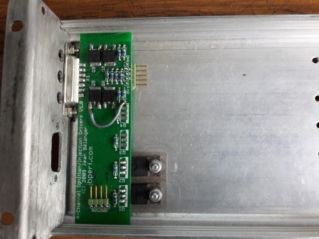
EDIT- photo of what Jean's 4 chanel board should look like once installed in the normal place. This one is for 4 injectors (ie, siamese staged) and two ignitors (Ford coilpack). Ignore the grey wire, it was someone else's board and there was a damaged trace I had to bypass.

4 channel by Rod Sugden, on Flickr.

Edited by Rod S on 8th Apr, 2018.

Schrödinger's cat - so which one am I ???


Nobby

17 Posts
Member #: 11671
Member

Hi Rod, thanks for your reply.

Yes it is the 4 channel board (not peak and hold).

Ok that sounds good, I will leave the components on as they are.

For future reference, is there a guide which describes which components are redundant if jeans 4 channel board is used? All I can find is a list of parts which need to be removed if you have a fully built board.

Thanks again,
Rob.


jbelanger

1267 Posts
Member #: 831
Post Whore

Montreal, Canada

You don't need anything used for the injector drivers or the ignition driver. These are all the components on this schematics page: http://www.msextra.com/doc/pdf/html/MS2V30...re-3.4-170.html and the ignition driver components on the following page.

Jean

http://www.jbperf.com/


Rod S

User Avatar

5988 Posts
Member #: 2024
Formally Retired

Rural Suffolk

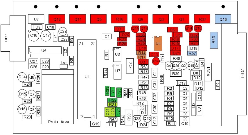
For future reference, here's a pictorial view that I did for someone a few years ago who was going to use Jean's 4 channel driver board, I've tidied it up a bit since I first did it (in case you come across it anywhere else) and you can cross reference it to the schematics Jean has mentioned.

pcbv3_clock_Inj_Ign (Small) by Rod Sugden, on Flickr

green is the old MS1 crystal/clock circuit, it is not needed at all on any MS2 or MS3 as they have the crystal/clock on their daughterboards. If you want to use an MS2 in 4 channel sequential mode (in our case that would only be if you wanted siamese STAGED injection) it MUST be removed. This is because the 4 channel modification requires access to two of the pins on the 40 pin socket which are connected to this circuit for an MS1 chip but not connected to anything on the MS2 daughterboard. Looking again at your photo you've installed the four capacitors, not a problem unless you want to do staged injection on your setup, if you do, remove them. Technically the light green ones could stay but in the schematics Jean referred to, but another page down, it does say to remove them all (and by removing them all it frees up another spare pin, useful if you ever want to do a further modification to the daughterboard to gain additional I/O as it becomes an alternative to other suggested spare pins)

red and orange is the complete injector drive circuitry on the schematic Jean referred to and simply isn't needed once you use his 4 channel board.

light blue is the single standard coil driver, again, not required with Jean's 4 channel board.

And just for completeness (although it doesn't apply to you) if you were using Jean's P&H board all the above also applies except it doesn't have any ignition drivers so you would have to add them yourself, either on any of the spare space you would now have on the heatsink or on the lid of the case (my preference because the P&H board uses the lid as it's heatsink anyway, just like the ignition drivers on the 4 channel board).

EDIT - typo

Edited by Rod S on 8th Apr, 2018.

Schrödinger's cat - so which one am I ???


Nobby

17 Posts
Member #: 11671
Member

Hi guys, thanks for your replies, really appreciate it.

Changing the subject a little, could someone direct me to a BOM for Jean's 4 channel board?

Thanks
Rob


jbelanger

1267 Posts
Member #: 831
Post Whore

Montreal, Canada

I'll put here the reply I sent to your email about the BOM. And maybe Rod has some recommendations about actual part numbers from a UK vendor.

There is no BOM published other than the quick description in the assembly section here: http://www.jbperf.com/quad_ign_inj/index.html. All the resistors locations are sized for 1/8 W resistors. R1-4 are 300R or 1k resistor depending on the IGBT you're using (IGBT are Q1-4). R5-8 are 1k. R9-12 are 100k. R13-16 are 15R. U1 and U2 are TC4427 chip such as these: https://ca.mouser.com/_/?Keyword=TC4427AVOA

As for the injector drivers (Q5-8), the part to use if you need to have the same thing as what is in the Microsquirt or on the MS3X is the VND5N07. However, if they will be the only drivers you use (so no need to match existing ones), you might want to use the VND14NV04 as it should be more robust.

http://www.jbperf.com/


Rod S

User Avatar

5988 Posts
Member #: 2024
Formally Retired

Rural Suffolk

I can give you Farnell (UK) part numbers for any of the parts used on the board, Farnell are probably best as they do free delivery to non-account holders for +£20 orders. RS similar pricing but I don't normally use them so I don't have a list of their numbers readily available.
But I need to be sure exactly how you are proceeding.
I presume from earlier in the thread you have a basic EDIS type coilpack so the TC4427 chips on Jean's newer board are simply not required (see my earlier photo of an early board that just does dumb coils, not logic level).
But as per all the un-necessary parts on your mainboard, are you intending to use Jean's 4 channel board because you actually want 4 channels (ie, staged injection) or just because it's easier than the standard board ?
I'm asking because I don't want to send you a list of parts which may not be need for whatever it is you have in mind.

Schrödinger's cat - so which one am I ???


Nobby

17 Posts
Member #: 11671
Member

Hi Rod,

I'm using Jean' s board because I'm doing port injection and staged, so two injectors in each inlet port, each needing independent control.

Yes it's a basic edis coil pack.

Thanks,
Rob


Rod S

User Avatar

5988 Posts
Member #: 2024
Formally Retired

Rural Suffolk

OK,
In which case you need to fully understand which bits you need to remove from the board as in the most recent photo and where to connect the wires up to Jean's board.
Also you have to modify the MS2 daughterboard to do this. The modification is quite simple if you are used to soldering SMD parts (just two short wires on top of an SMD part) but it must be right before you can use the staged setup.
I'll do a list of Farnell part numbers tomorrow.

Schrödinger's cat - so which one am I ???


Rod S

User Avatar

5988 Posts
Member #: 2024
Formally Retired

Rural Suffolk

IGBTs
I've been using IRGB14C40LPBF in all my projects so far (I think it was Jean who originally suggested them many years ago) but although Farnell list them (their code 8650829) they are out of stock and on a very long lead time. A bit strange as I bought two only 4 months or so ago for another project. An alternative I've seen mentioned on a couple of automotive engine management type forums is the ISL9V5036. In fact a quick search on the MS-E forums brings them up in a post by Jean as being suitable (but the post I found is three years old). They are in stock under code 2454180. They are specifically for automotive applications according to their datasheet and looks like a 1K gate resistor should suffice. But I have to stress I have no personal experience of them yet (but I will add a couple to my next order to find out.....)

Injector drivers
The VND5N07 are Farnell code 2629755 and in stock. The VND14NV04 are code 1739408 but, again, out of stock.
Although the VND5N07 has been well used in the past, there have been reported failures. In fact the board in my photo above had one fail, the damaged trace was as a result of replacing it (not by me I hasten to add....). IIRC the VND14NV04 have a higher avalanche energy rating so will take more abuse. Personally I don't use either as I use low-z injectors (which are driven with a different type of transistor) so can't really comment on the failure(s).

Stock level issues at Farnell have been getting worse for quite some time now, Although they are convenient (I have an account so don't even have to make a £20 minimum order for free next day delivery) recently I've been using DigiKey or Mouser, they both have UK web ordering and the VAT/duty is all done by them even though it's shipped from the USA, the only downside is a £35 (last time I used them) minimum order and 4-5 day wait for transatlantic shipping.

For the 1/8W resistors I use the Multicomp MF12 series, metal film and 1% tolerance. Slightly more expensive than a 5% carbon resistor but (supposedly) a bit more stable.
330R 9343032 (EDIT - typo, value corrected)
1K 9342400
100k 9342427
You won't need the 15R or the TC4427 chips unless you change from a "dumb" EDIS coilpack to something modern, logic level.

If you bought just the bare PCB, unless it's changed substantially since I last built one (ages ago) you will also need a male DB15 connector, the solder bucket type rather than the normal PCB mount type - the solder buckets slip over the top and bottom of the PCB then you solder "underneath" the buckets - and it needs to be one with short buckets or they will come too far back on the PCB.
The only one I've found at Farnell that suits is 1348013 but it has no built in nuts for fitting thumbscrews etc so you need some of these 2099518 or pull apart some cards from a scrap older style PC....

Also I strongly suggest you use a plug/socket arrangement - the green pin headers in my photo - to connect to the mainboard. If you solder both ends of the wires it's a nightmare assembling or dismantling the MS2 case as this board ends up rigidly bolted to the lid.
Try these for the pin bits, 3418479 and then 1593508, 1593509 and 1593529 for the plug bits. Or again, raid an old style AT or ATX scrap PC, they used the same style plugs for buttons, speaker etc to the motherboards.

And don't forget micas 520214 (or the modern silicon version 522636) between the IGBTs and the case lid.

Edited by Rod S on 11th Apr, 2018.

Schrödinger's cat - so which one am I ???


jbelanger

1267 Posts
Member #: 831
Post Whore

Montreal, Canada

The ISL9V5036 is what I used in the full kit and I've never had any issue reported on them. And you want to use a 1k resistor with them (R1-4).

http://www.jbperf.com/


Nobby

17 Posts
Member #: 11671
Member

Hi Everyone,

Many thanks for your replies. I really appreciate the time you have put into helping me out.

I have now removed the necessary components around the clock circuit. I got carried away when following the MS Extra assembly guide!

I have generated a list of components and their locations on the board but I’m struggling with R5-R8.

Q1-4 IGBT (ISL9V5036)
Q5-Q8 Injector Drivers (VND5N07)
R1-R4 1K Resistor
R9-R12 100K Resistor
R5-R8 ???

Thanks,
Rob


jbelanger

1267 Posts
Member #: 831
Post Whore

Montreal, Canada

R5-8 are 1k resistors.

http://www.jbperf.com/


jbelanger

1267 Posts
Member #: 831
Post Whore

Montreal, Canada

I should add that the DB-15 connector I used on the board is this one: https://www.digikey.ca/products/en?keywords...171-015-102L011

You can also use 171-015-103L011 which is nickel plated instead of tin plated. Either one will have the correct hardware to fit on the board but you will need to add the jack screws.

Edited by jbelanger on 11th Apr, 2018.

http://www.jbperf.com/


Rod S

User Avatar

5988 Posts
Member #: 2024
Formally Retired

Rural Suffolk

On 11th Apr, 2018 jbelanger said:
R5-8 are 1k resistors.


Interesting Jean.
I would have given the same answer based on the Microsquirt and MS3X schematics and the VND5N07 datasheet, but the board I have in front of me has 330R resistors.
Not mine, I just inherited it as a dead board from an attempt to replace a failed VND5N07 which damaged a trace on the PCB, so I bridged the trace and added the plug connectors to do some testing (which went OK) but I wonder if the use of a 330R resistor was the root cause of the failure ?
I don't know if the board was originally sourced as a kit or just a plain PCB (probably the latter).

Schrödinger's cat - so which one am I ???


jbelanger

1267 Posts
Member #: 831
Post Whore

Montreal, Canada

The goal in using 1k is mostly to make the driver as identical to the other MS drivers as possible and use something that agrees with the datasheet. A 330R resistor would probably increase switching speed somewhat but there is no way this would cause a failure in the trace you saw; it's still limiting current to 15mA at most with a 5V signal.

http://www.jbperf.com/


Rod S

User Avatar

5988 Posts
Member #: 2024
Formally Retired

Rural Suffolk

The trace failure was nothing to do with the resistor value, it was just from a previous attempt to un-solder the failed VND5N07 (the soldering iron appears to have damaged the trace during removal)
I'm just wondering if the higher base/gate current might have helped the VDN5N07's early demise.
I guess the answer is stick with the 1K base and don't risk other quoted values.

Schrödinger's cat - so which one am I ???


jbelanger

1267 Posts
Member #: 831
Post Whore

Montreal, Canada

I'm sorry, I misunderstood the origin of the failed trace.

The VND5N07 seems to somewhat lack robustness even with the 1k base resistor so I would agree that it's probably best not to experiment with different resistance values. And the potentially faster switching with the lower resistance might increase the instantaneous flyback current which the VND5N07 might not like.

http://www.jbperf.com/


Nobby

17 Posts
Member #: 11671
Member

Hi All,

I'm about to connect the 4 channel board to the main board using the header and plug method described by Rod.

I can find the info for where the injector pins get connected so that's sorted. Do I connect the gnd to the gnd on the proto area?

I am using a ford coil pack with wasted spark so do I need to connect the ignition header to the main board? Or can i use the ignition drivers on the main board?

Thanks
Rob


jbelanger

1267 Posts
Member #: 831
Post Whore

Montreal, Canada

The ground on the DB15 goes to the car ground. The ground pin on the driver board goes to the MS board ground so the proto area ground is a good choice.

If you have the needed drivers already installed on your main board there is no need to use the driver board.

Jean

http://www.jbperf.com/


Rod S

User Avatar

5988 Posts
Member #: 2024
Formally Retired

Rural Suffolk

On 29th Apr, 2018 Nobby said:
I am using a ford coil pack with wasted spark so do I need to connect the ignition header to the main board? Or can i use the ignition drivers on the main board?

The standard mainboard, even if fully assembled, only has one high voltage/current ignitor (Q16).
To run wasted spark on any "dumb" coilpack (like the EDIS one) you use two ignitors - two of the locations on Jean's board in this case - and connect them to D14 and D16 as per the manual (the manual will say to connect via resistors but they're already on Jean's board). The settings in TunerStudio for wasted spark take care of swapping the CPU outputs to make D14 and D16 the ignition outputs in the correct sequence.

I'm out this morning but I'll do a photo later of how I did it (the other half of the case to my photo above).

Schrödinger's cat - so which one am I ???


Nobby

17 Posts
Member #: 11671
Member

Hi Guys,

I'm almost there but I'm struggling with where to connect the injector 1 and 2 leads from Jean's board to the main board and also the two ignition leads. Ive tried to figure it out from the manual but im struggling a bit.

Thanks,
Rob


jbelanger

1267 Posts
Member #: 831
Post Whore

Montreal, Canada

You need to connect them to R32 and R36 respectively as per this picture on my web site: http://www.jbperf.com/sequential/v3_0_inj_outputs.png It is also in the MS2/Extra manual but the resolution is bad there.

I assume you have also made the other modifications described here: http://www.jbperf.com/sequential/index.html#ms2mods (Again this is also in the manual)

Jean

http://www.jbperf.com/

Home > A-Series EFI / Injection > MS2 Assembly Headache - Ignition drivers
Users viewing this thread: none. (+ 1 Guests)   Next ->
To post messages you must be logged in!
Username: Password:
Page: