| Page: |
| Home > Show Us Yours! > OT - CNC Router | |||||||
|
1391 Posts Member #: 1686 Post Whore Oxford |
2nd Jun, 2014 at 10:41:16pm
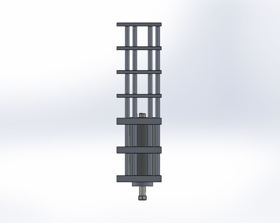
I just like to share my current project with you and on the advice of Custard to explain the background behind the project here goes.
Edited by Sam on 8th Jun, 2014. On 19th Feb, 2011 Miniwilliams said:
OMG Robert that's a big one |
||||||
|
283 Posts Member #: 8215 Senior Member Rayleigh |
5th Jun, 2014 at 12:49:02pm
Impressive stuff Sam
Dave the Cake |
||||||
 902 Posts Member #: 111 Post Whore Loughborough |
5th Jun, 2014 at 03:54:00pm
I work for a company which does the cable tracking you see down the axis of this kind of machine. If you need some let me know, i'll see if i can swing you a "sample" |
||||||
 562 Posts Member #: 9285 Post Whore Oxfordshire |
5th Jun, 2014 at 07:42:00pm
Nice project, i'd like to see updates! My build thread: http://www.turbominis.co.uk/forums/index.php?p=vt&tid=454802
|
||||||
|
1391 Posts Member #: 1686 Post Whore Oxford |
8th Jun, 2014 at 09:50:04pm
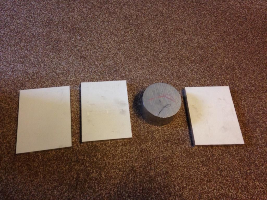
So first bit of progress!
On 19th Feb, 2011 Miniwilliams said:
OMG Robert that's a big one |
||||||
|
1391 Posts Member #: 1686 Post Whore Oxford |
8th Jun, 2014 at 10:15:28pm
On 19th Feb, 2011 Miniwilliams said:
OMG Robert that's a big one |
||||||
|
283 Posts Member #: 8215 Senior Member Rayleigh |
8th Jun, 2014 at 11:39:06pm
That all sounds really interesting Sam, nice vids. Can't believe how quick that chomps through the alu!
Dave the Cake |
||||||
|
4314 Posts Member #: 700 Formerly British Open Classic The West Country |
9th Jun, 2014 at 06:32:32am
For the uneducated amongst us, what's the difference between a router and a milling machine, is it just a case that in a router the cutting head moves and in a mill the work piece moves? Isambard Kingdom Brunel said:
Nothing is impossible if you are an Engineer |
||||||
|
1391 Posts Member #: 1686 Post Whore Oxford |
9th Jun, 2014 at 04:07:02pm
More the spindle motor to be honest and really a case of strength as a result.
On 19th Feb, 2011 Miniwilliams said:
OMG Robert that's a big one |
||||||
|
1391 Posts Member #: 1686 Post Whore Oxford |
9th Jun, 2014 at 06:16:31pm
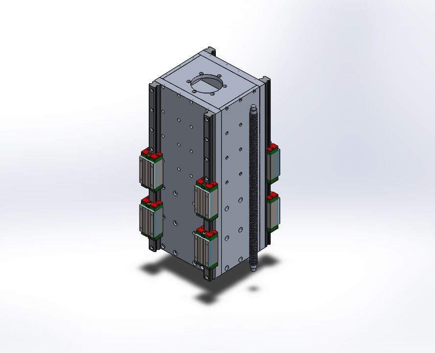
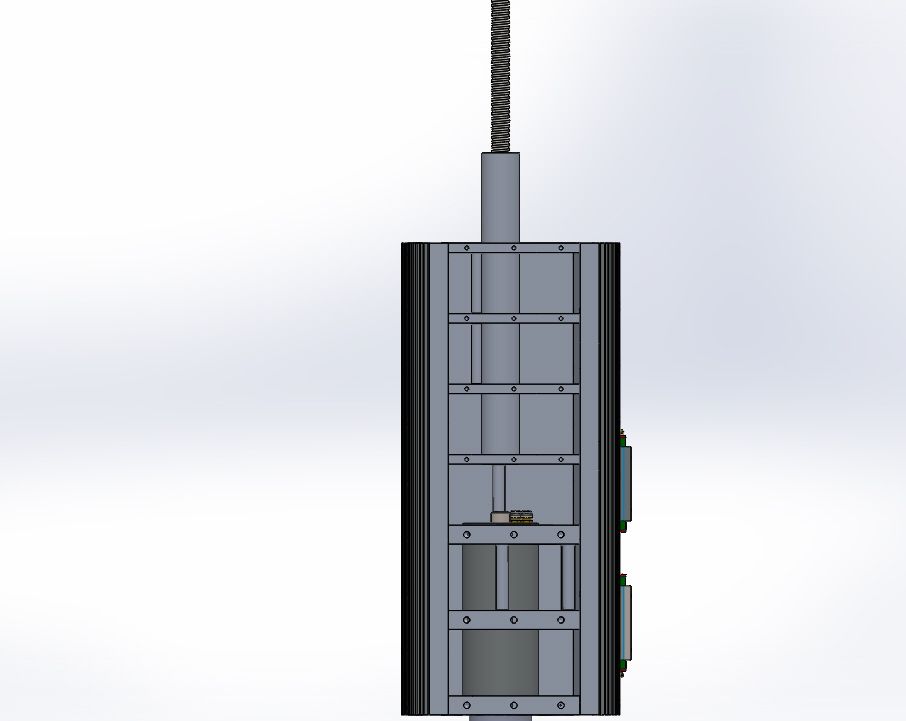
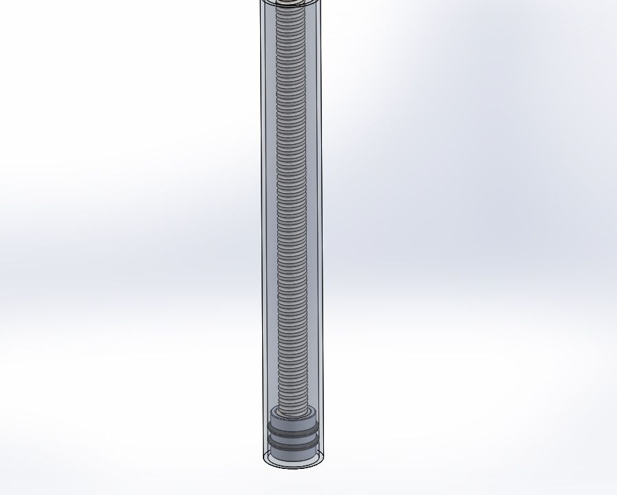
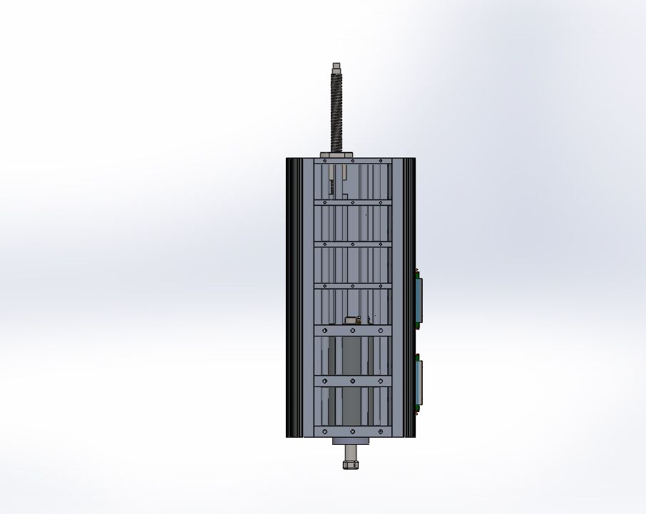
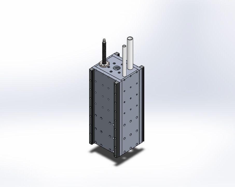
Today's progress. Modeled the ball screws profile rails and blocks from pdf drawings and chucked them into the assembly document.
On 19th Feb, 2011 Miniwilliams said:
OMG Robert that's a big one |
||||||
 270 Posts Member #: 69 Senior Member Coventry |
10th Jun, 2014 at 10:31:53am
so basically to make body kits? couldnt you just use a CNC router to cut the wooden forms and then place the foams in between and then use a hot wire to run down each pair of wooden forms and hot wire the foams to match? seems simpler |
||||||
|
1391 Posts Member #: 1686 Post Whore Oxford |
10th Jun, 2014 at 03:32:47pm
That's exactly the plan for those parts. But i need this to be quite a multi purpose machine. So mostly working on sheet materials. But with the odd occasion where I can pop a 4th axis down the length of it and machine up table legs or something.
On 10th Jun, 2014 skolawn said:
so basically to make body kits? couldnt you just use a CNC router to cut the wooden forms and then place the foams in between and then use a hot wire to run down each pair of wooden forms and hot wire the foams to match? seems simpler On 19th Feb, 2011 Miniwilliams said:
OMG Robert that's a big one |
||||||
|
1391 Posts Member #: 1686 Post Whore Oxford |
12th Jun, 2014 at 02:30:35pm
Sorry custard I completely ignored your question about my job. I'm a mechanical engineering apprentice, currently in my second year out of four total. But I've never been trained on how to use any CAD software. Ive learnt by picking it up and having a go pretty much.
Edited by Sam on 12th Jun, 2014. On 19th Feb, 2011 Miniwilliams said:
OMG Robert that's a big one |
||||||
 16540 Posts Member #: 4241 King Gaycharger, butt plug dealer, Sheldon Cooper and a BAC but generally a niceish fella if you dont mind a northerner Rotherham, South Yorkshire |
12th Jun, 2014 at 07:41:43pm
On 12th Jun, 2014 Sam said:
Would anyone be interested in me producing a step by step guide with how to get yourself off the ground with solid works? Yes please. 
On 11th Feb, 2015 robert said:
i tried putting soap on it , and heating it to brown , then slathered my new lube on it 
|
||||||
|
1391 Posts Member #: 1686 Post Whore Oxford |
12th Jun, 2014 at 10:37:10pm
It times out if you take too long writing a post, bollocks!
On 19th Feb, 2011 Miniwilliams said:
OMG Robert that's a big one |
||||||
|
1391 Posts Member #: 1686 Post Whore Oxford |
13th Jun, 2014 at 04:20:05pm
Just priced up the rails for the machine.
On 19th Feb, 2011 Miniwilliams said:
OMG Robert that's a big one |
||||||
|
1391 Posts Member #: 1686 Post Whore Oxford |
10th Jul, 2014 at 01:24:41pm
Ive not been sitting idle on this. Ive had a few weeks off to get on with other things. But I'm back into it.
On 19th Feb, 2011 Miniwilliams said:
OMG Robert that's a big one |
||||||
|
1391 Posts Member #: 1686 Post Whore Oxford |
16th Jul, 2014 at 09:40:39pm
On 19th Feb, 2011 Miniwilliams said:
OMG Robert that's a big one |
||||||
|
1391 Posts Member #: 1686 Post Whore Oxford |
20th Jul, 2014 at 08:57:02pm
On 19th Feb, 2011 Miniwilliams said:
OMG Robert that's a big one |
||||||
|
1391 Posts Member #: 1686 Post Whore Oxford |
9th Aug, 2014 at 10:36:14pm
So sick of looking at a computer screen now.
On 19th Feb, 2011 Miniwilliams said:
OMG Robert that's a big one |
||||||
 4890 Posts Member #: 1775 Post Whore Chester |
10th Aug, 2014 at 06:31:17am
Omg nice work there I run a supercharger and I don't care the TB is on the wrong side.
|
||||||
|
283 Posts Member #: 8215 Senior Member Rayleigh |
10th Aug, 2014 at 07:08:30pm
Incredible! Dave the Cake |
||||||
|
1391 Posts Member #: 1686 Post Whore Oxford |
10th Aug, 2014 at 10:17:47pm
Cheers fellas. But honestly its not all too hard. Just a lot of work thus a lot of repetition.
Edited by Sam on 10th Aug, 2014. On 19th Feb, 2011 Miniwilliams said:
OMG Robert that's a big one |
||||||
|
1391 Posts Member #: 1686 Post Whore Oxford |
17th Aug, 2014 at 01:06:26am
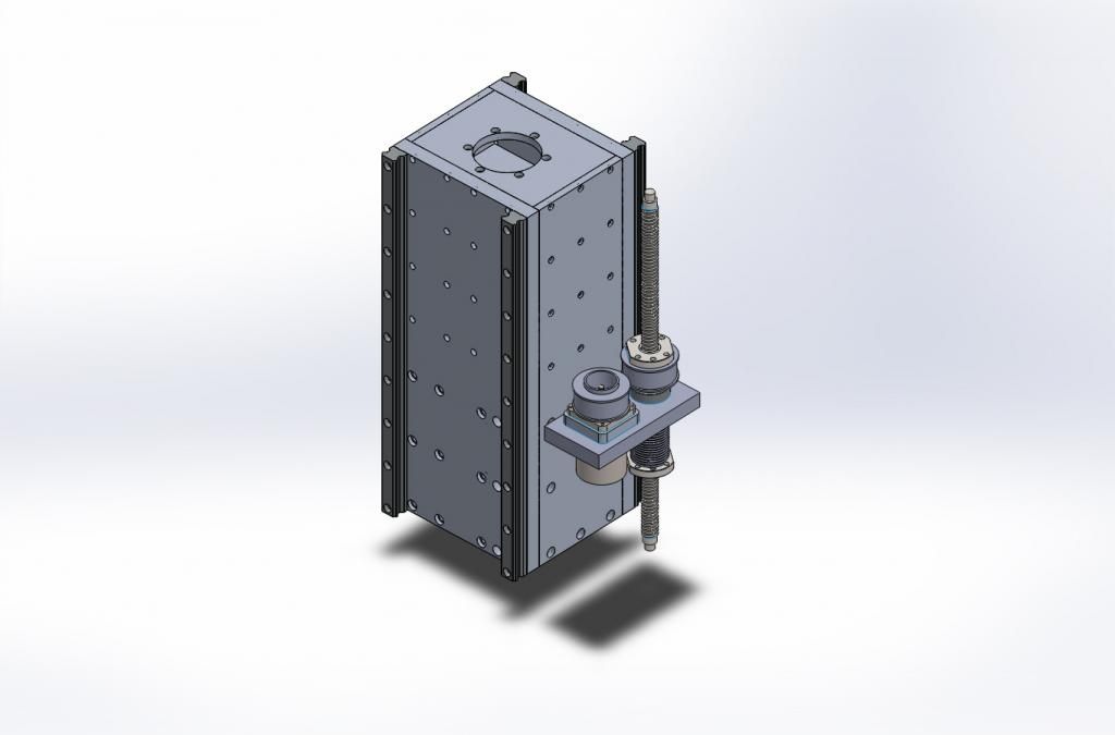
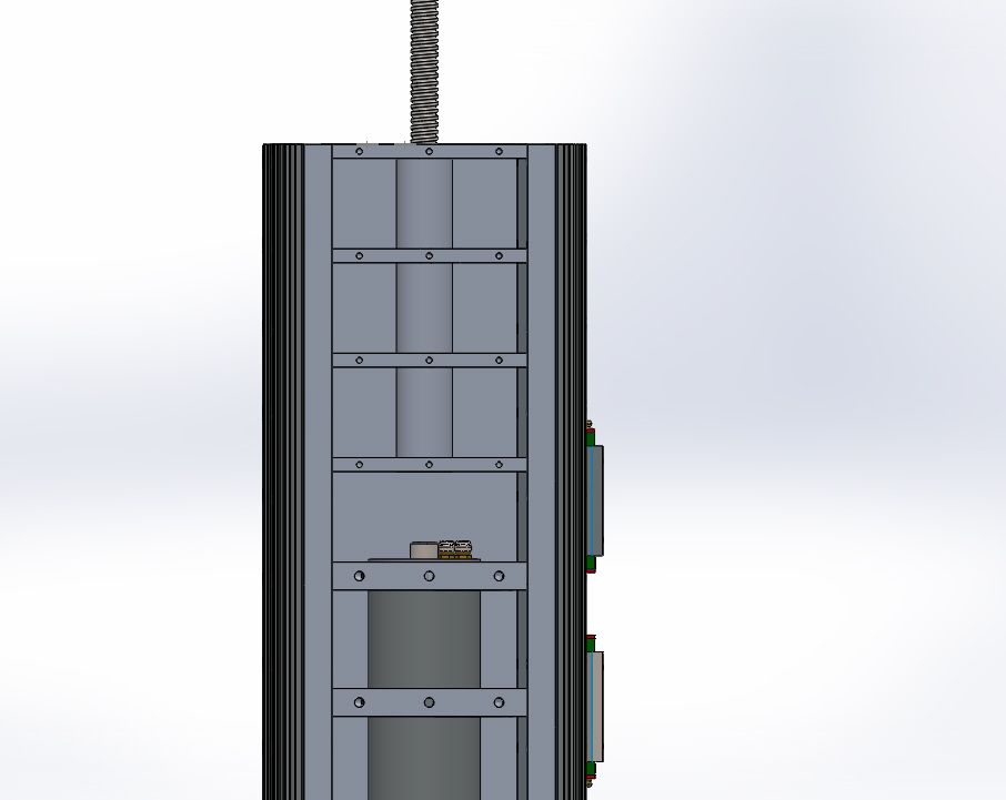
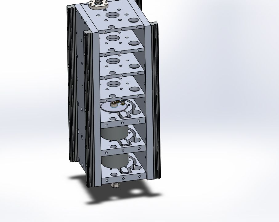
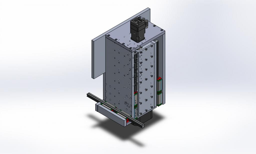
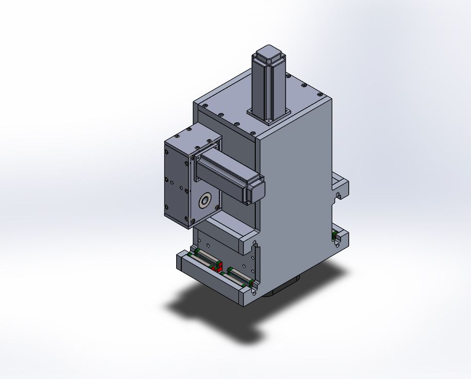
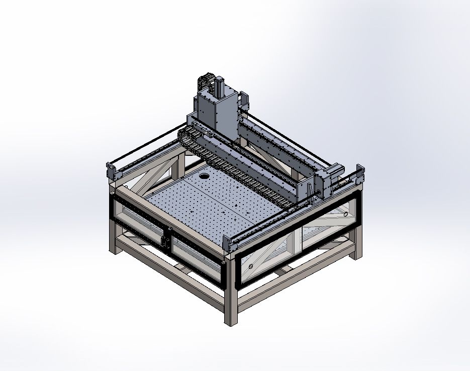
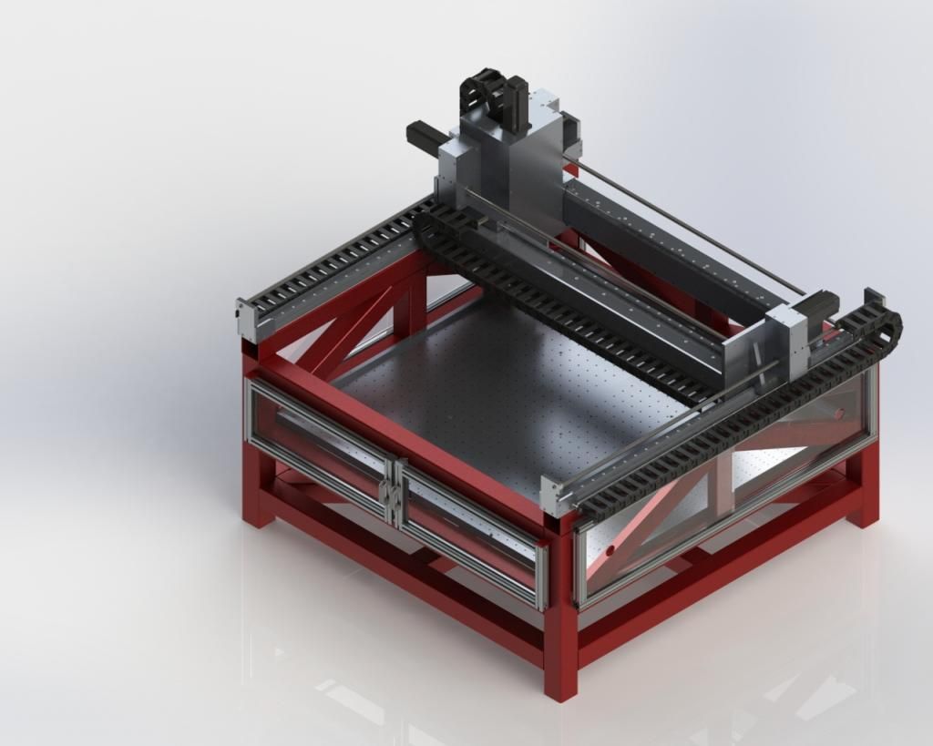
Alright, jobs done. Render time.
On 19th Feb, 2011 Miniwilliams said:
OMG Robert that's a big one |
||||||
|
1391 Posts Member #: 1686 Post Whore Oxford |
17th Aug, 2014 at 08:52:43am
On 19th Feb, 2011 Miniwilliams said:
OMG Robert that's a big one |
||||||
| Home > Show Us Yours! > OT - CNC Router | |||||||
|
|||||||
| Page: |


