Donations towards server fund so far this month.

 
£0.00 / £100.00 per month
Page:
Home > A-Series EFI / Injection > MS extra siamese sequential tune (msq) to start with

gemertw

User Avatar

77 Posts
Member #: 7659
Advanced Member

Netherlands

Hi,
I just finished building my port injected inlet manifold and I am ready to connect my MSII extra with the latest sequential code to the engine. Everything has beens tested and seems to work.
First some engine specs:
1380CC A-Plus, Kent md 286sp cam, 1.5 full roller rockers, belt driven cam, stage 3 head with Rimflow in and exhaust valves, omega cast pistons, Ultru light flywheel/back plate, MED 36-1 crank wheel, carbon fibre pushrods and Isky followers. 50mm 'Nissan' throttle body. Delphi injectors 42lb/hour with regulated fuel supply (between 2.5 and 4 bar).

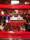
I am new to injection but read about everything I could find on this subject on the internet. I added a picture of the engine with the homemade inlet manifold. ( the Edis system visible is bypassed and sits there doing nothing)

Now for my question, Can anybody help me to get a Tunerstudio tune(.msq file) that has proven to work so I can use that as a reference to check my settings and to have a better point to start from. (Preferably from a n.a. engine.)

Regards,
Will


Attachments:


Joe C

User Avatar

12307 Posts
Member #: 565
Carlos Fandango

Burnham-on-Crouch, Essex

Paul S or Rod S are the ones to advise here (as i'm sure you are aware)

It will be very interesting to see how you get on with this engine with its long cam duration and the siamese code :)

On 28th Aug, 2011 Kean said:
At the risk of being sigged...

Joe, do you have a photo of your tool?


http://www.turbominis.co.uk/forums/index.p...9064&lastpost=1

https://joe1977.imgbb.com/


jbelanger

1267 Posts
Member #: 831
Post Whore

Montreal, Canada

As mentioned, Paul or Rod are the ones who can help with an msq.

You don't mention it but do you have a cam position sensor? If not you'll have to run in semi-sequential mode which will work but won't be optimal.

Another thing you don't mention is the lambda sensor. And that should actual be sensorS since you want to be able to measure the AFR of the inner and outer cylinders to get the correct injection timing.

By the way, that looks like a nice setup and I also look forward to hear how it goes.

Jean

http://www.jbperf.com/


Rod S

User Avatar

5988 Posts
Member #: 2024
Formally Retired

Rural Suffolk

Hi Will,

Nice setup, your inlets/plenum looks very similar to my initial one only neater !!!

Jean's question about the cam position sensor is very important. From the front view of your engine there isn't one in the dizzy drive hole so have you incorporated one elsewhere (ie, in the chain drive sprocket) ???

If not, I'm sure Paul will say something about his early experience with the semi-sequential mode but, all the development now is with the fully sequential mode needing a cam sensor, ie, I haven't even tried the semi-sequential mode.

Also, as Jean says, you will need two widebands to be able to monitor and data log the inner and outer cylinders independantly to be able to set the siamese code parameters correctly. And on a normally aspirated it's a lot easier to install two suitably placed than on a turbo setup !!!

So giving you an msq that will allow the engine to start - provided it has a cam sensor for fully sequential - is not a problem but, you will need dual widebands to then make it useable.

One more question, do you have a JimStim ???

It is invaluable in setting the msq nearly right before starting because it not only generates the 36:1 crank signal but also generates the cam (phase) signal so you can get (or confirm) the injector sequence is correct and see the injector timings moving as expected.

Rod.

Schrödinger's cat - so which one am I ???


gemertw

User Avatar

77 Posts
Member #: 7659
Advanced Member

Netherlands

Thanks for your reaction,
On the pictures the distributor is indeed blanked of this is an old picture from before a read everything about siamese ports and sequential injection. At this moment the distributor is back in and has the cam sensor integrated in it. I just received yesterday the welding bung for my second wb lambda probe so indeed I’ am going to run with two. The only thing worrying me at this moment is injector size because the 286 narrows down the injection window by another 10 degrees and I did my initial calculation thinking I could have 85% duty cycle which is not true at all. So I’ am hoping that a fuel pressure off 4 bar will compensate enough otherwise I need two bigger injectors.
I was thinking that setting timing trigger to mid pulse and injection timing to fixed timing, injection timing 1 to 106 (full inlet lift on cyl two), injection timing 2 to 286 (full inlet lift on cyl one) would be the best setting to start from and then using the ve trim tables to get equal afr on inner and outer cylinders. Would you agree on this? Today I am hooking up my digital scope to the engine (no plugs and no fuel) to see if all timing points are correct and to have a look at all the critical signals. I used shielded cable everywhere where I found it might be necessary and ran the critical cables apart from each other.

regards Will


gemertw

User Avatar

77 Posts
Member #: 7659
Advanced Member

Netherlands

Hi Rod did not read your last question, Yes I've got a jimstim and everything seems to be working well on, two short flashes on inj. 1 followed by two on inj two.

regards Will


Rod S

User Avatar

5988 Posts
Member #: 2024
Formally Retired

Rural Suffolk

On 6th Dec, 2009 gemertw said:
Hi Rod did not read your last question, Yes I've got a jimstim and everything seems to be working well on, two short flashes on inj. 1 followed by two on inj two.


Good, sounds like you have the wheel settings correct in the msq (I got it all wrong at first...). You also need to check the phase (cam) is correct relative to (1&2) vs (3&4) ie, that you are not 360 degrees out on the full cycle. You can just about see it on the JimStim if you run it slow enough and hook the second trigger up to a spare LED, but obviously it relies on the trigger on the engine being correct and not 180 degrees (camshaft/dizzy) out. If you have a scope this is dead easy to check on the engine of course.

Injectors are too small I'm afraid other than for quite low output. If my conversion is correct they are only 440cc/min. Paul does all the fancy maths (!!!) but I reckon that's only good for ~50BHP with the actual duty cycle.

I'll dig out my original injector timing settings for when I test ran normally aspirated on a very similar manifold in a minute but they were different to yours from memory.

Rod.

Schrödinger's cat - so which one am I ???


Rod S

User Avatar

5988 Posts
Member #: 2024
Formally Retired

Rural Suffolk

+45 degrees (INJ1) and 0 degrees (INJ2) was my starting point on normally aspirated. MG Metro cam but injectors up close to the head like yours.

I completely mis-understood what the timing figures meant initially and Paul and Jean had to set me right, see this thread, especially the second page.

http://www.turbominis.co.uk/forums/index.p...tid=295719&fr=0

(that was on Megatune, obviously I'm on TunerStudio now)

EDIT - BTW, the reason the injection timings are not valve full lift is (a) because of the transit time down the port (b) the offset is to overcome the charge robbing.

The hardest part for me initially was understanding just what the settings were relative to (as per the other thread).

Edited by Rod S on 6th Dec, 2009.

Schrödinger's cat - so which one am I ???


Paul S

User Avatar

8604 Posts
Member #: 573
Formerly Axel

Podland

There is not a lot that I can add to the above.

However, for some reason, it is not a good idea to take an .msq from one MS and load it to another. This has causes a lot of problems in the past.

Hence I suggest that you work out the best settings, download the default .msq from your MS and update the settings. If you can already see the jimstim LEDs flashing as you expect, then you are almost there.

Saul Bellow - "A great deal of intelligence can be invested in ignorance when the need for illusion is deep."
Stephen Hawking - "The greatest enemy of knowledge is not ignorance, it is the illusion of knowledge."


Paul S

User Avatar

8604 Posts
Member #: 573
Formerly Axel

Podland

Here is the injector capacity table from the up-coming build guide.


EDIT: Changed table

Edited by Paul S on 6th Dec, 2009.

Saul Bellow - "A great deal of intelligence can be invested in ignorance when the need for illusion is deep."
Stephen Hawking - "The greatest enemy of knowledge is not ignorance, it is the illusion of knowledge."


gemertw

User Avatar

77 Posts
Member #: 7659
Advanced Member

Netherlands

Hi,
Little testing done again
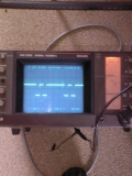
I already was afraid the injectors would be too small. I will just use them to get started and order two new ones when have found out how much too small they are. Just hooked up my scope and set things so that injection would occur at the same point of valve lift for cyl one and two and at a simulated 3000rpm the pulses are exactly 10mSec apart so that’s good (1/(3000/60))/2=10 the complete cycle of 720 degrees takes exactly 40mSec. I did not think of the travel time for the fuel so I suppose you are right that things must be advanced a bit and will start with the advised setting of opening 30 degrees after tdc and see what will happen.
With all the settings I have got at this moment the two pulses merge at a RPM of 4250 so completely theoretical that should ad up to 75bhp and that’s way short of the expected 115 at 7000 and I will have now timing flexibility left so the injectors are too small for sure.
As soon as I receive my second lambda I will fire her up!

Regards will


Attachments:


Paul S

User Avatar

8604 Posts
Member #: 573
Formerly Axel

Podland

I'm running four of those injectors on the 998 Turbo, assuming that they are the Mini MPi ones. I'm also running a short inlet duration cam which probably limits how much I can get out of them.

I run the hybrid single pulse mode as it is simpler to set up, one VE table and one Injection Timing table. I found it too complicated any other way.

My injection timing to get the pulse mid point at TDC is 130-170 degrees, so transit time is a lot higher than you are allowing.

The transit time is lower if you use pencil spray injectors, but that is unlikley. Most of the larger ones are cone.

Saul Bellow - "A great deal of intelligence can be invested in ignorance when the need for illusion is deep."
Stephen Hawking - "The greatest enemy of knowledge is not ignorance, it is the illusion of knowledge."


Joe C

User Avatar

12307 Posts
Member #: 565
Carlos Fandango

Burnham-on-Crouch, Essex

this is a great thread!

three people that know what they are doing are now working with the simaese code :)

On 28th Aug, 2011 Kean said:
At the risk of being sigged...

Joe, do you have a photo of your tool?


http://www.turbominis.co.uk/forums/index.p...9064&lastpost=1

https://joe1977.imgbb.com/


Rod S

User Avatar

5988 Posts
Member #: 2024
Formally Retired

Rural Suffolk

On 6th Dec, 2009 Paul S said:
I run the hybrid single pulse mode as it is simpler to set up, one VE table and one Injection Timing table. I found it too complicated any other way.
My injection timing to get the pulse mid point at TDC is 130-170 degrees, so transit time is a lot higher than you are allowing.


Paul,

Just to clarify (for my own benefit if nothing else !!!) your figures of 130 / 170 is mid pulse in single pulse mode whereas my figures of 45 / 0 is mid pulse in dual pulse mode ???

Just need to be sure in my own mind.

If I'm right, they still don't match exactly but I think part of our transit time differences is the actual position of the injectors - mine are cone too but I think slightly closer to the valves than yours.

Edited by Rod S on 6th Dec, 2009.

Schrödinger's cat - so which one am I ???


Paul S

User Avatar

8604 Posts
Member #: 573
Formerly Axel

Podland

Yes, mid pulse in single pulse mode. Using Injection Table 3 under the advanced menu.

The 130/170 was the range under N/A mode in June.

I was actually checking earlier and my injection timing at idle is now around 110 to 120 degrees. But then it is only 135 degrees at full chat on 1 bar boost. It goes up to 165 degrees maximum at high revs high vacuum. Still some work needed to tidy it up.

Edited by Paul S on 6th Dec, 2009.

Saul Bellow - "A great deal of intelligence can be invested in ignorance when the need for illusion is deep."
Stephen Hawking - "The greatest enemy of knowledge is not ignorance, it is the illusion of knowledge."


Rod S

User Avatar

5988 Posts
Member #: 2024
Formally Retired

Rural Suffolk

The 110 to 120 in single pulse mode makes a much better comparison to the dual pulse figures (45/0) I got to work at idle if my maths is right, ie, average of ours is now about 90 degrees apart.
I "think" that's what I was expecting, but I've been wrong before...... !!!

This is getting embarrasing though, despite all the work on the engine and code I still haven't finished the car to put it in, must get my finger out so to speak or I'm not even going to be in the top 10 for having it running on the road....

Schrödinger's cat - so which one am I ???


gemertw

User Avatar

77 Posts
Member #: 7659
Advanced Member

Netherlands

Paul,
To get my thinking right about your figures when you are saying you have the timing at idle at 110 degrees midpuls this means midpuls for cylinder one is at 110 degrees after tdc on the intake stroke of cyl one.
With the average camshaft being timed in between 103 to 106 degrees for full lift on the intake of cyl one this means midpuls occurs at 4 to 7 degrees after full lift? if that is so than i do not understand your timing at high refs I would expect it to come earlier instead of later. If on the other hand you mean that midpuls at idle occurs at 110 degrees before tdc than this sound as way to early because this is even before the middle of the intake stroke of cyl two and at idle port travel times are not that much relevant. (if I got the interpretation right on the numbers on Jean's site http://www.jbperf.com/sequential/index.html.
Regards Will


Paul S

User Avatar

8604 Posts
Member #: 573
Formerly Axel

Podland

No, thats 110 degrees before TDC and that pulse feeds the inner and outer cylinder on that port.

So a mid pulse timing of 110 degrees represents the transit at idle. The pulse must reach the valve around TDC to give equal fuel to each cylinder.

However, that does not take account of the fuel delivered off the wall of the port *oh well*

Saul Bellow - "A great deal of intelligence can be invested in ignorance when the need for illusion is deep."
Stephen Hawking - "The greatest enemy of knowledge is not ignorance, it is the illusion of knowledge."


Rod S

User Avatar

5988 Posts
Member #: 2024
Formally Retired

Rural Suffolk

Will,

The "single" pulse mode Paul runs averages the innner and outer cylinders.

The default setting is DUAL (corrected from earlier typo as per Jeans post below) pulse, just like the plot on your scope earlier, one pulse per cylinder.

So the timings will inevitably be different in the two modes, the single pulse mode is the "average" of the two, simplistically...

I'll post some plots of the two from my scope tomorrow.

EDIT - I'll try and re-phrase that...

If you look at the scope plot you posted, the two pulses were independant so they both had their own timing figures. If you increased fuelling or RPM until the pulses merged (which is a really bad thing hence Jean re-writing the code to allow a transition to single pulse mode) the timing figures change, hence the third table that Paul mentioned earlier.

Edited by Rod S on 8th Dec, 2009.

Schrödinger's cat - so which one am I ???


gemertw

User Avatar

77 Posts
Member #: 7659
Advanced Member

Netherlands

I thought I was starting to understand things but now I am afraid I have got two stupid questions. First is where do you set dual pulse mode?? I expected it to be under engine constants squirts per cycle but when I set this from two to four nothing changes on my scope. :(
Second one is, when you say your injection timing at idle is 120 degrees this means you have +120 in the 'fixed injection timing 1' field under sequential injection?? As I understand Jeans code this means mid puls occurs 130 degrees before tdc of cyl one and that is 46 degrees before full lift on the intake of cyl two?

Regards Will


jbelanger

1267 Posts
Member #: 831
Post Whore

Montreal, Canada

Dual pulse mode is the default mode and what you were seeing on the scope (I think Rod's message has a typo and that is what he meant). To set single mode, you go to the sequential injection window in the Advanced menu and set the RPM at which the code will switch from dual pulse mode to single pulse mode.

And the timing is set either in the same window if using a single value or in table 3 if you want timing to change with RPM and load. And since this is a single pulse for both cylinders in the port, you want it to be centered on the overlap between the 2 intake events while taking into account the transit time. This is where the 110 degrees comes from and it is BTDC of cylinder 1.

Jean

http://www.jbperf.com/


gemertw

User Avatar

77 Posts
Member #: 7659
Advanced Member

Netherlands

Hi Jean,
Thanks for the explanation that sounds very logical. Also Pauls single pulse numbers make sense now because the middle of the opening of inlet valves of cyl 1 and 2 is around 15 degrees atdc of cyl 1 so when Paul has an injection timing of 0 to 45 in single pulse mode this means he is injecting 15 to 60 degrees before that point and that again sounds like normal travel time figures:). The 110 to 120 degrees in dual pulse mode (when aiming for mid pulse at full lift) adds up to a travel time of 36 to 46 degrees (with the cam timed in for full lift on cyl one at 106 degrees (normal setting)). 106-180=-74 110-74= 36! 120-74=46!.
Now only for my other question when I am changing the number of squirts per engine cycle, under basic settings, to 4 squirts instead of two I see no change in the actual number of injection pulses on my scope, I expected to get two more per cycle!

Regards Will


Rod S

User Avatar

5988 Posts
Member #: 2024
Formally Retired

Rural Suffolk


On 6th Dec, 2009 jbelanger said:
Dual pulse mode is the default mode and what you were seeing on the scope (I think Rod's message has a typo and that is what he meant).


Yes, typo, sorry - too much alcohol and too late....

What you see on your scope (Will) is dual pulse and the default.

If you put your scope on the MS2 outputs running the JimStim you can clearly see the change from dual pulse to single and see the effect in TunerStudio too - try it with the change set at 5k RPM and you will see the injection timings change (depending on how you set the third table) and the pulse width switch from being split betwen pulse width one and pulse width two to all being on pulse width one.

Schrödinger's cat - so which one am I ???


Paul S

User Avatar

8604 Posts
Member #: 573
Formerly Axel

Podland

I hope you guys are going to persevere with the dual pulse mode.

I could not get it to work at above 3000rpm, but that was with an early version of the code that may not have been handling the pulses merging as expected.

Another problem is that although in theory you have a VE table and an Injection Timing table for Inner and Outer cylinders respectively, they do not operate independantly. If you change settings to improve the AFR on the inner cylinders, then the AFR on the outers also change.

Saul Bellow - "A great deal of intelligence can be invested in ignorance when the need for illusion is deep."
Stephen Hawking - "The greatest enemy of knowledge is not ignorance, it is the illusion of knowledge."


jbelanger

1267 Posts
Member #: 831
Post Whore

Montreal, Canada

Will,

You can't change the number of squirts using the basic settings. This will only affect the req. fuel setting.

The number of squirts is established automatically in the code depending on the settings: in dual pulse mode, there are 2 squirts per cycle (one per cylinder) and in single pulse mode there is one squirt per cycle (one for both cylinders). You can't change that because then the code wouldn't know how to time the other squirts.

Jean

http://www.jbperf.com/

Home > A-Series EFI / Injection > MS extra siamese sequential tune (msq) to start with
Users viewing this thread: none. (+ 2 Guests)   Next ->
To post messages you must be logged in!
Username: Password:
Page: